Ap1513, Ordering information, Pin descriptions – Diodes AP1513 User Manual
Page 2: Pwm control 2a step-down converter
AP1513
PWM CONTROL 2A STEP-DOWN CONVERTER
AP1513 Rev. 4
2 of 9
JULY 2009
DS31053
www.diodes.com
©
Diodes Incorporated
Lead-free
Ordering Information
AP1513 S X - 13
Package
Packing
13 : Tape & Reel
S : SOP-8L
Lead Free
L : Lead Free
G : Green
Device
Package
Code
Packaging
(Note 2)
13” Tape and Reel
Quantity
Part Number Suffix
AP1513SL-13 S SOP-8L
2500/Tape
&
Reel
-13
AP1513SG-13 S SOP-8L
2500/Tape
&
Reel
-13
Notes: 1. EU Directive 2002/95/EC (RoHS). All applicable RoHS exemptions applied. Please visit our website at
http://www.diodes.com/products/lead_free.html.
2. Pad layout as shown on Diodes Inc. suggested pad layout document AP02001, which can be found on our website at
http://www.diodes.com/datasheets/ap02001.pdf
.
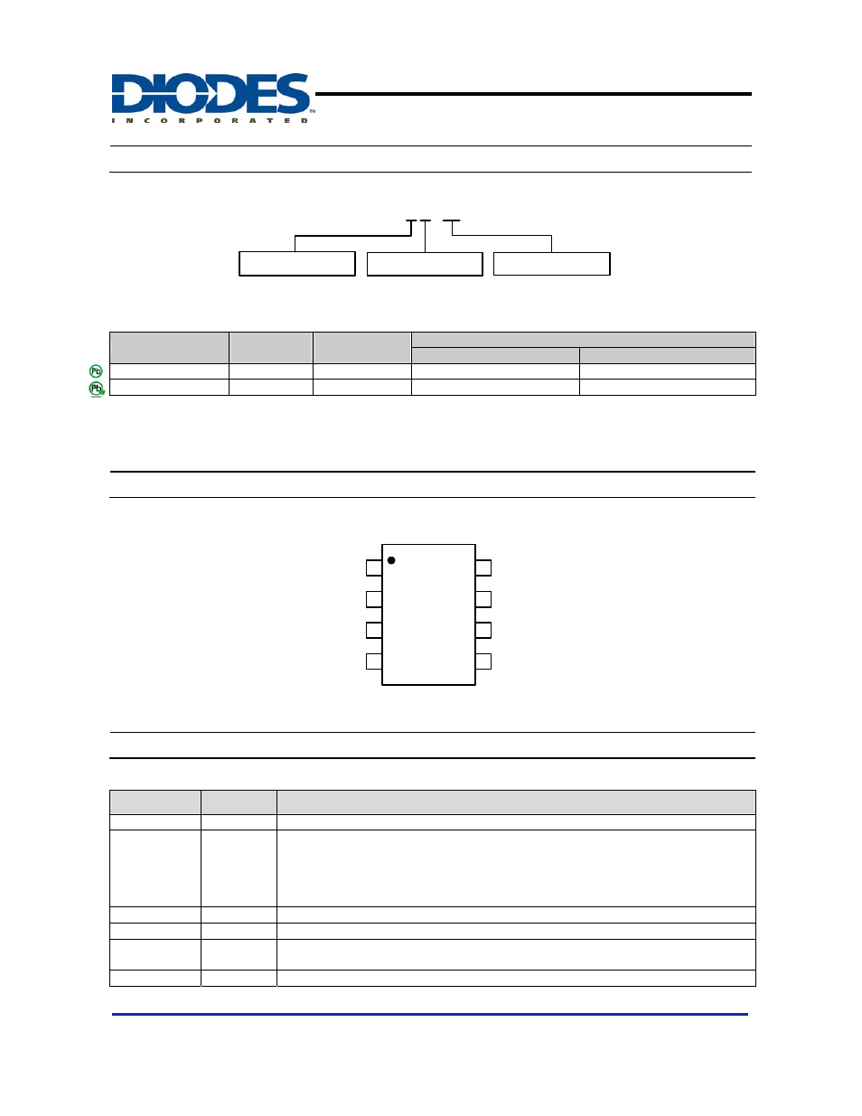
Pin Descriptions
( Top View )
1
2
3
4
8
7
6
5
FB
Output
OCSET
AP1513
Output
EN
Vss
Vss
V
CC
SOP-8L
Pin Descriptions
Pin Name
Pin No.
Description
FB 1
Feedback
pin
EN 2
Power-off pin
H: Normal operation
(Step-down operation)
L: Step-down operation stopped
(All circuits deactivated)
OCSET
3
Add an external resistor to set max output current
V
CC
4
IC power supply pin
Output 5,
6
Switch Pin. Connect external inductor/diode here. Minimize trace area at this pin
to reduce EMI
V
SS
7,
8
GND
Pin