Diodes AP1513 User Manual
Ap1513, Typical application circuit, Features
AP1513
PWM CONTROL 2A STEP-DOWN CONVERTER
AP1513 Rev. 4
1 of 9
JULY 2009
DS31053
www.diodes.com
©
Diodes Incorporated
•
Input voltage: 3.6V to 18V
•
Output voltage: 0.8V to V
CC
•
Duty ratio: 0% to 100% PWM control
•
Oscillation frequency: 300KHz typ.
•
Soft-start, Current limit, Enable function
• Thermal
Shutdown
function
•
Built-in internal SW P-channel MOS
•
SOP-8L: Available in “Green” Molding Compound
(No Br, Sb)
•
Lead Free Finish/ RoHS Compliant (Note 1)
AP1513 consists of step-down switching regulator with PWM
control. These devices include a reference voltage source,
oscillation circuit, error amplifier, and internal PMOS.
AP1513 provides low-ripple power, high efficiency, and excellent
transient characteristics. The PWM control circuit is able to vary
the duty ratio linearly from 0 up to 100%. This converter also
contains an error amplifier circuit as well as a soft-start circuit that
prevents overshoot at startup. An enable function, an over
current protect function and a short circuit protect function are built
inside, and when OCP or SCP happens, the operation frequency
will be reduced from 300KHz to 30KHz. Also, an internal
compensation block is built in to minimum external component
count.
With the addition of an internal P-channel Power MOS, a coil,
capacitors, and a diode connected externally, these ICs can
function as step-down switching regulators. They serve as ideal
power supply units for portable devices when coupled with the
SOP–8L mini-package, providing such outstanding features as
low current consumption. Since this converter can accommodate
an input voltage up to 18V, it is also suitable for the operation via
an AC adapter.
• PC
Motherboard
• LCD
Monitor
• Graphic
Card
• DVD-Video
Player
• Telecom
Equipment
• ADSL
Modem
•
Printer and other Peripheral Equipment
• Microprocessor
core
supply
•
Networking power supply
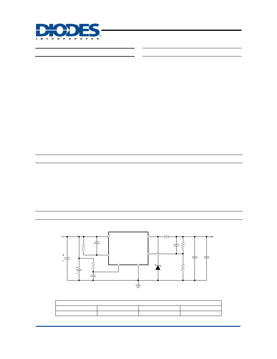
Typical Application Circuit
AP1513
+
-
V
SS
EN
C
C
R
A
R
B
D1
SBR2U30P1
FB
Vcc
Output
CVcc
V
OUT
= 5V/2A
V
IN
R
OCSET
OCSET
C
OUT
C
IN
Optional
C
OCSET
C
EN
R
EN
Option
100K
Note: V
OUT
= V
FB
x (1+R
A
/R
B
)
R
B
=0.7K~5K ohm
L1
33uH
6.8K
1.3K
3K
0.1uF
+
-
C
0.1uF
470uF
470uF
0.1uF
V
IN
= 12V, I
MAX
= 2A
V
OUT
2.5V 3.3V 5V
L1 Value
22uH 27uH 33uH
Features
General Description
Applications