Data sheet, Pin configuration, Pin description – Diodes AP3586A/B/C User Manual
Page 2
Data sheet
Single Phase Synchronous Buck PWM Controller AP3586A/B/C
Mar. 2012 Rev. 1. 1 BCD Semiconductor Manufacturing Limited
2
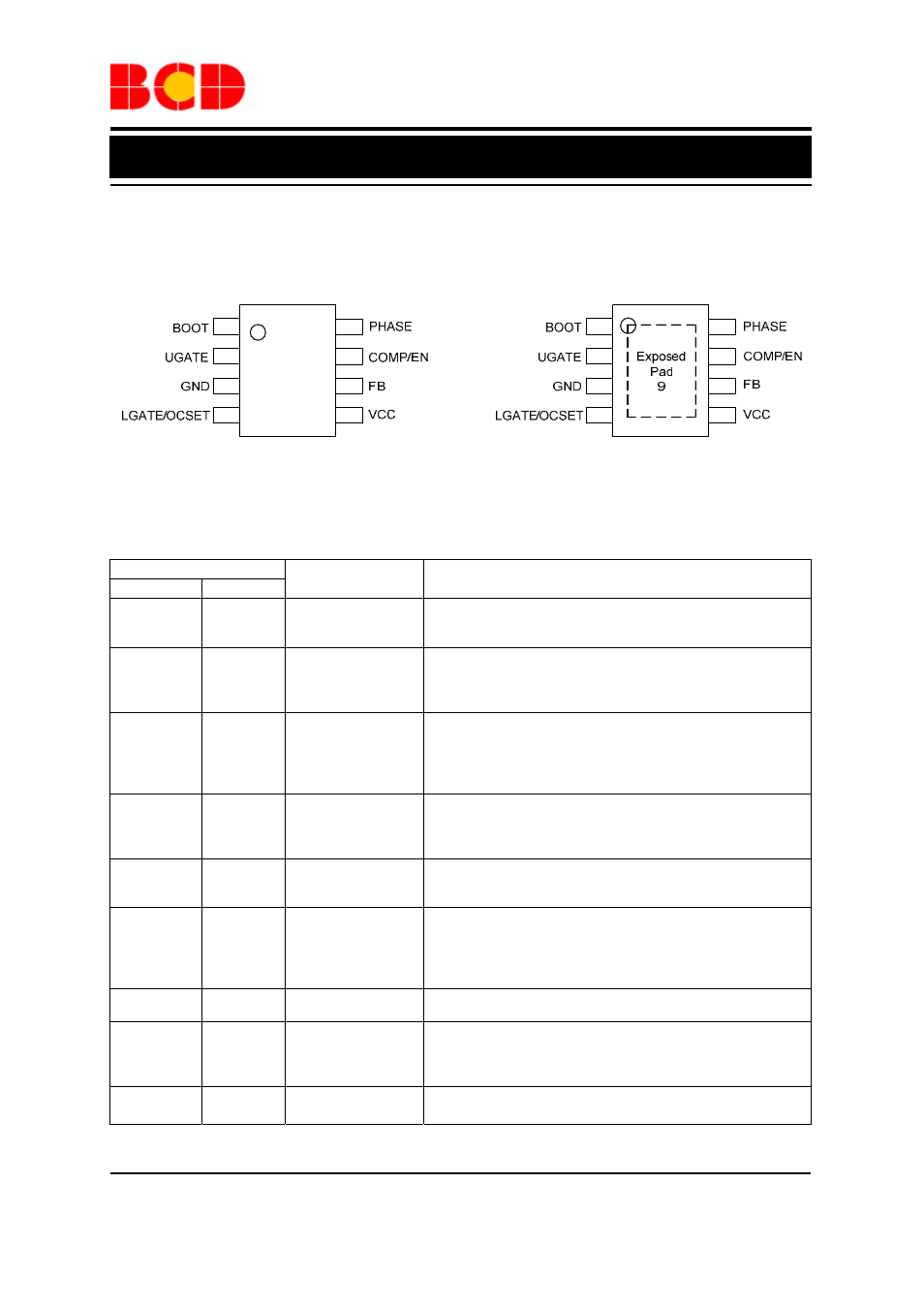
Pin Configuration
MP Package
(PSOP-8)
1
2
3
4
8
7
6
5
1
2
3
4
8
7
6
5
Figure 2. Pin Configuration of AP3586A/B/C (Top View)
Pin Description
Pin Number
SOIC-8 PSOP-8
Pin Name
Function
1 1 BOOT
Bootstrap pin. Connect a bootstrap capacitor from this pin to
PHASE for creating a BOOT voltage suitable to drive a standard
N-Channel MOSFET.
2 2 UGATE
Upper-gate drive pin. Connect this pin to the upper MOSFET gate
providing the gate drive. This pin is monitored by the adaptive
shoot-through protection circuitry to determine when the upper
MOSFET has turned off.
3 3 GND
Ground for the IC. All voltage levels are measured with respect to
this pin. Connect this pin directly to the low side MOSFET source
and ground plane with the lowest impedance. The exposed pad
must be soldered to a large PCB and connected to GND for
maximum power dissipation.
4 4
LGATE/OCSET
Low-side Gate Driver Output and Over-Current Setting Input.
This pin is the gate driver for low-side MOSFET. It is also used to
set the maximum inductor current. Refer to the section in
“Function Description” for detail.
5 5 VCC
Bias supply pin. Provides a 5V or 12V bias supply for the chip
from this pin. The pin should be bypassed with a capacitor to
GND.
6 6
FB
Feedback pin. This pin is the inverting input of the internal error
amplifier. Use FB pin, in combination with the COMP pin, to
compensate the voltage control feedback loop of the converter. A
resistor divider from output to GND is used to set the output
voltage.
7 7 COMP/EN
Compensation and disable pin. This pin is the output of the Error
Amplifier. Pull COMP pin low will shut down the IC.
8 8 PHASE
This pin connects to the source of the upper MOSFET and the
drain of the lower MOSFET. This pin is also monitored by the
adaptive shoot-through protection circuitry to determine when the
upper MOSFET has turned off.
9
Exposed
Pad
Exposed Pad as ground pin.
M Package
(SOIC-8)