Byy57a / byy58a – Diodes BYY58A User Manual
Page 4
BYY57A / BYY58A
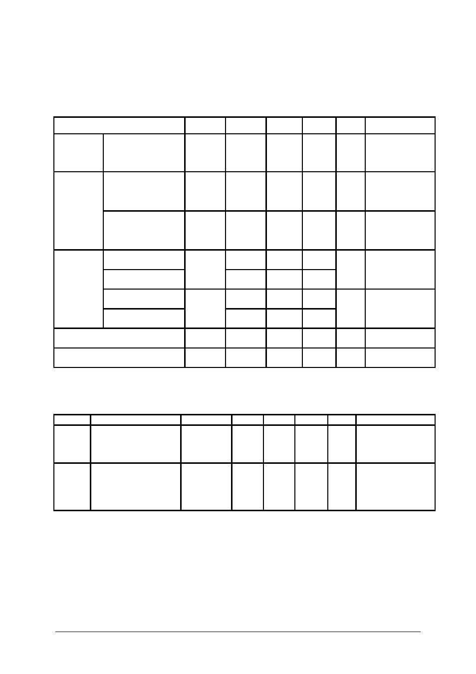
Electrical characteristics
(at T
amb
= 25°C unless otherwise stated)
Parameter Symbol
Min.
Typ.
Max.
Unit
Test
contitions
Forward
voltage
BYY57A-75...800
BYY58A-75...800
V
F
- 1.05
1.15
V
I
F
= 50 A,
measuring time
10ms (half-sine
wave)
BYY57A-75...800
BYY58A-75...800
V
F
-
0.810
- V
I
F
= 20 A,
measuring time
10ms (half-sine
wave),T
J
= 150°
Forward
voltage
(information
values)
BYY57A-75...800
BYY58A-75...800
V
F
- -
1.2
V
I
F
= 75 A
BYY57A-75...150
BYY58A-75...150
- - 3
BYY57A-200...800
BYY58A-200...800
I
RRM
- -
1.5
mA
T
J
= 150°C, at
V
RRM
BYY57A-75...400
BYY58A-75...400
- -
0.25
Reverse
current
BYY57A-500...800
BYY58A-500...800
I
RRM
- -
0.1
mA at
V
RRM
Threshold voltage (information
value)
V
(FO)
- 0.66 - V
T
J
= 175°C
Slope resistance (information
value)
r
F
- 4.5 -
mΩ T
J
= 175°C
Options: Electrical characteristics for parallel connecting
(at T
amb
= 25°C unless otherwise stated)
Option Parameter Symbol
Min.
Typ.
Max.
Unit
Test
contitions
1 Forward
voltage
difference in one
category of forward
voltage
∆V
F
- -
0.05
V
I
F
= 50 A, measuring
time 10ms (half-sine
wave)
2
Reverse current in one
category of forward
voltage (only for
BYY57A-300…800 and
BYY58A-300…800)
I
R
- -
0.01
mA
at
V
RRM
Issue 2 – November 2006
4
www.zetex.com
© Zetex Semiconductors plc 2006