New prod uc t, Znbg4003, Typical characteristics – Diodes ZNBG4003 User Manual
Page 4: Application information
ZNBG4003
Document number: DS35007 Rev. 1 - 2
4 of 6
June 2012
© Diodes Incorporated
NEW PROD
UC
T
A Product Line of
Diodes Incorporated
ZNBG4003
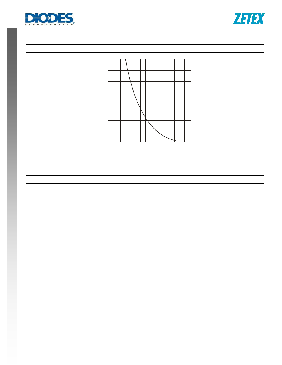
Typical Characteristics
(measured @ T
AMB
= +25°C, V
CC
= 5.0V)
100
1000
10
R
CAL
Drain Current vs. R
CAL
15
0
5
10
D
R
AI
N
C
U
R
R
EN
T
(mA
)
Application Information
Above is a partial applications circuit for the ZNBG4003 showing
all external components needed for biasing one of the four FET
stages available. Each bias stage is provided with a gate and
drain pin. The drain pin provides a regulated 2.0V supply that
includes a drain current monitor. The drain current taken by the
external FET is compared with a user selected level, generating a
signal that adjusts the gate voltage of the FET to obtain the
required drain current. If for any reason, an attempt is made to
draw more than the user set drain current from the drain pin, the
drain voltage will be reduced to ensure excess current is not
taken. The gate pin drivers are also current limited.
The bias stages are split up into two pairs, with the drain current of
each pair set by an external R
CAL
resistor. R
CAL
1 sets the drain
currents of stages 1 and 3, whilst R
CAL
2 sets the drain currents of
stages 2 and 4. This allows the optimisation of drain currents for
differing tasks such as input stages where noise can be critical
and later amplifier stages where gain may be more important.
A graph showing the relationship between the value of R
CAL
and I
D
is provided in the Typical Characteristics section of this datasheet.
The ZNBG4003 includes a switched capacitor DC-DC converter
that is used to generate the negative supply required to bias
depletion mode FETs used in common source circuit configuration
as shown above. This converter uses two external capacitors, C
NB
the charge transfer capacitor and C
SUB
the output reservoir
capacitor. The circuit provides a regulated -2.5V supply both for
gate driver use and for external use if required (for extra discrete
bias stages, mixer bias, local oscillator bias etc.). The -2.5V
supply is available from the C
SUB
pin.
If any bias stages are not required, their gate and drain pins may
be left open circuit. If all bias stages associated with an R
CAL
resistor are not required, then this resistor may be omitted.
To ease PCB layout, the pinout for the ZNBG4003 includes two
V
CC
pins. These pins are internally connected so only one of the
pins needs to be powered for the device to function. It is probable
that the extra pin will help avoid the need for trace cross-over
components or ground plane disruption from reverse side PCB
links. Note that the exposed pad of the package must be either left
floating or connected to C
SUB
.