Diodes ZNBG6001 User Manual
Page 6
ZNBG4000
ZNBG4000 ZNBG4001
ZNBG6000 ZNBG6001
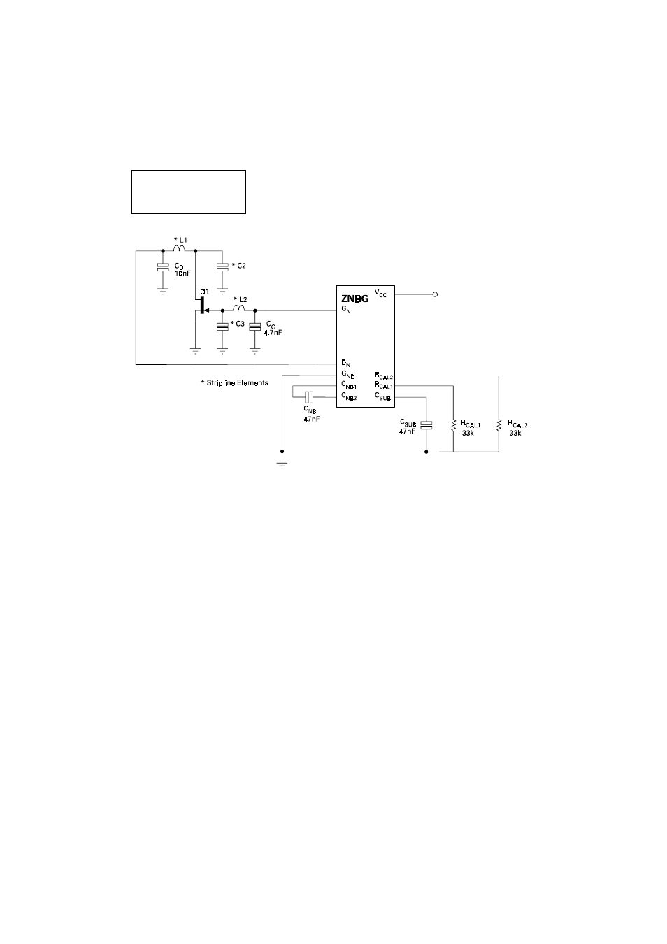
TYPICAL APPLICATION CIRCUIT
APPLICATIONS INFORMATION
The above is a partial application circuit for the ZNBG series showing all external components
required for appropriate biasing. The bias circuits are unconditionally stable over the full
temperature range with the associated FETs and gate and drain capacitors in circuit.
Capacitors C
D
and C
G
ensure that residual power supply and substrate generator noise is not
allowed to affect other external circuits which may be sensitive to RF interference. They also
serve to suppress any potential RF feedthrough between stages via the ZNBG device. These
capacitors are required for all stages used. Values of 10nF and 4.7nF respectively are
recommended however this is design dependent and any value between 1nF and 100nF could
be used.
The capacitors C
NB
and C
SUB
are an integral part of the ZNBGs negative supply generator. The
negative bias voltage is generated on-chip using an internal oscillator. The required value of
capacitors C
NB
and C
SUB
is 47nF. This generator produces a low current supply of approximately
-3 volts. Although this generator is intended purely to bias the external FETs, it can be used to
power other external circuits via the C
SUB
pin.
Resistors R
CAL1/2
sets the drain current at which all external FETs are operated. Both ZNBG devices
have the facility to program different drain currents into selected FETs. Two R
CAL
inputs are
provided. For the ZNBG4000, resistor R
CAL1
sets the drain current of FETs 1 and 2, resistor R
CAL2
sets the drain current of FETs 3 and 4. For the ZNBG6000, resistor R
CAL1
sets the drain current
of FETs 1 and 4, resistor R
CAL2
sets the drain current of FETs 2, 3, 5 and 6. If the same drain current
is required for all FETs on either device then pins R
CAL1
and R
CAL2
can be wired together and
shunted to ground by a single calibration resistor of half normal value.
If any bias control circuit is not required, its related drain and gate connections may be left open
circuit without affecting the operation of the remaining bias circuits. If all FETs associated with
a current setting resistor are omitted, the particular R
CAL
should still be included. The supply
current can be reduced, if required, by using a high value R
CAL
resistor (e.g. 470k).
4-142