Zlnb2012 – Diodes ZLNB2012 User Manual
Page 7
FURTHER INFORMATION
Inputs Vpol1 and Vpol2 are designed to be wired to the
power inputs of an LNB via a high value (1K) resistors.
Input Vpol1 controls outputs HOR1, BHOR1 and ENA1.
Input Vpol2 controls outputs HOR2, BHOR2 and ENA2.
With either input voltage set at or below 14V, the
corresponding HOR pin will be active and the
corresponding BHOR pin will be the inverse of HOR.
With either input voltage at 14.5V or higher, the
corresponding HOR pin will be active and the
corresponding BHOR pin will be the inverse. Should
the voltage applied to either Vpol input fall below 8V,
the corresponding ENA (enable) pin will be low,
otherwise these outputs will remain high. Any input or
output may be left open circuit without any effect on
the remaining circuitry.
The ZLNB2012 includes all the circuitry necessary to
detect the presence of a 22kHz tone modulated on the
supply input to the LNB. The main elements of the
detector are an op-amp, a rectifier/smoother and a
comparitor. The op-amp has a pre-set internal
feedback resistor so that just a simple RC network
wired to the input gives user defined gain and low
frequency cut filter characteristics.
The RC network components also serve two other
purposes. The resistor provides overvoltage
protection for the Vpol pin and the capacitor minimises
tone interference of the Vpol threshold. The upper
frequency roll-off of the op-amp has been set internally
at above 100kHz to allow the amplifier to be used with
other common tone switch frequencies.
The rectifier/smoother/comparitor function is provided
by a complex propriety circuit that allows the
ZLNB2012 to reliably detect wanted tones whilst
ignoring low frequency square wave switch box
signals, DiSEqC™ bursts and supply switching
transients common when using DiSEqC-2™ ready
set-top boxes. This is all achieved without the need for
any further external components. The threshold of the
comparitor is supply dependent, hence the gain of the
preceding op-amp must be adjusted in line with supply
voltage.
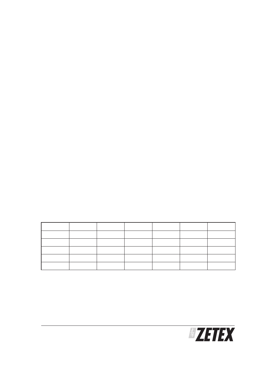
Output Truth Table
The ZLNB2012 includes two independent channels, each containing a voltage detector and tone detector. The
following truth table applies to each channel:-
PROVISIONAL ISSUE A - OCTOBER 2001
ZLNB2012
7
Tone
Vpol
TD
BTD
HOR
BHOR
ENA
Off
р14V
Low
High
Low
High
High
Off
у14.5V
Low
High
High
Low
High
On
р14V
High
Low
Low
High
High
On
у14.5V
High
Low
High
Low
High
-
<8V
-
-
Low
High
Low