Typical characteristics, Test circuit for open loop voltage gain, Stability boundary condition – Diodes ZTL432 User Manual
Page 4: Gain vs. frequency, Pulse response, Test circuit for pulse response
ZTL431/ZTL432
Document number: DS33263 Rev. 16 - 2
4 of 10
May 2013
© Diodes Incorporated
A Product Line of
Diodes Incorporated
ZTL431/ZTL432
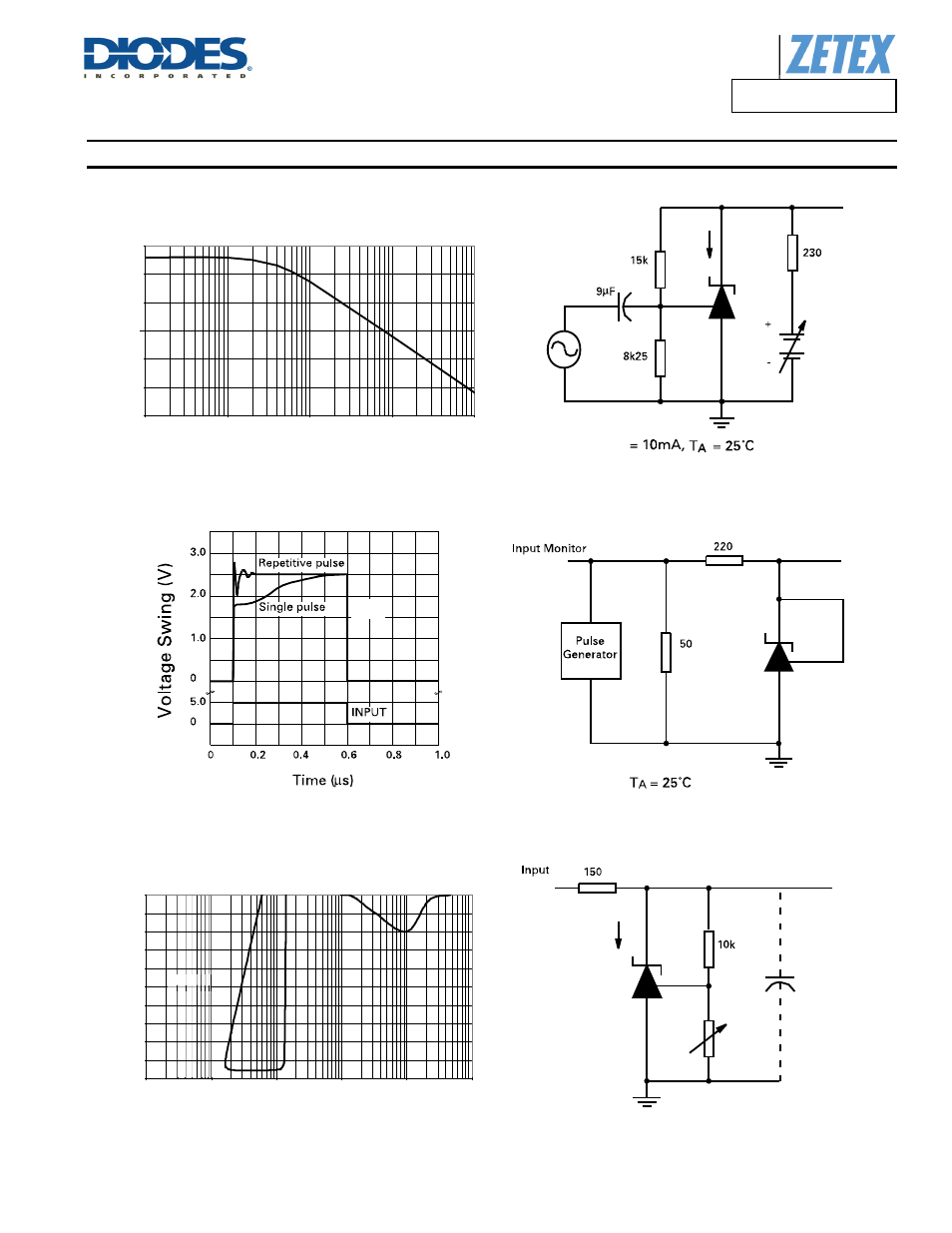
Typical Characteristics
(cont.)
I
KA
I
KA
I
KA
V
KA
V
KA
V
REF
< V
KA
< 20, I
KA
= 10mA, T
A
= 25°C
V
KA
V
KA
Stability Boundary Condition
0
10
20
30
40
50
60
70
80
90
100
10.0E-12
100.0E-12
1.0E-9
10.0E-9
100.0E-9
1.0E-6
Load Capacitance (F)
Cat
hode
Cur
ren
t(
m
A
)
Gain vs. Frequency
0
10
20
30
40
50
60
100
1000
10000
100000
1000000
Frequency (Hz)
Gain
(dB
)
Stable
ab ee
Stable
Pulse Response
Test Circuit for Stabilty Boundary Conditions
Test Circuit for Pulse Response
Test Circuit for Open Loop Voltage Gain
This manual is related to the following products: