Application information, Zxre060, A product line of diodes incorporated – Diodes ZXRE060 User Manual
Page 7
ZXRE060
0.6V ADJUSTABLE PRECISION SHUNT REGULATOR
ZXRE060
Document number: DS33611 Rev. 6 - 2
7 of 12
March 2011
© Diodes Incorporated
A Product Line of
Diodes Incorporated
Application Information
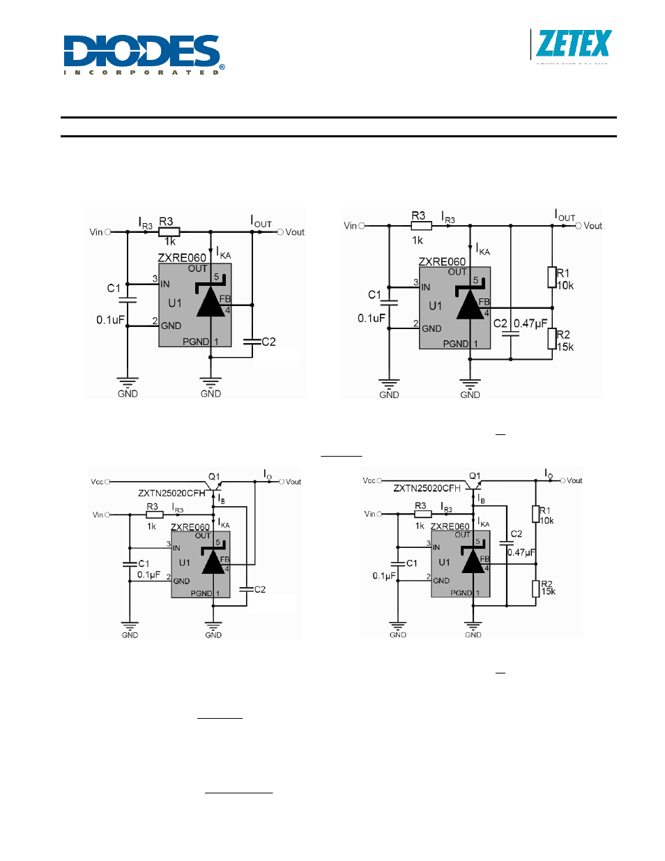
The following show some typical application examples for the ZXRE060. It is recommended to include the compensation
capacitor C2 to guarantee stability. C2 may range in value from 0.1µF to 10µF depending on the application. The time constant
formed by C2 and R3 should be greater than 1ms multiplied by the feedback factor R2/(R1 + R2).
Both C1 and C2 should be as close to the ZXRE060 as possible and connected to it with the shortest possible track. In the case
of fig 9 and fig10, it means the opto-coupler will have to be carefully positioned to enable this.
Figure 3. 0.6V Shunt Regulator
Figure 4. 1.0V Shunt Regulator
REF
V
OUT
V
=
⎟
⎠
⎞
⎜
⎝
⎛ +
=
2
R
1
R
1
REF
V
OUT
V
3
R
I
OUT
V
IN
V
3
R
−
=
Figure 5. 0.6V series LDO regulator
Figure 6. 1.0V series LDO regulator
REF
V
OUT
V
=
⎟
⎠
⎞
⎜
⎝
⎛ +
=
2
R
1
R
1
REF
V
OUT
V
Design guides
1. Determine
I
OUT
and choose a suitable transistor taking power dissipation into consideration.
2. Determine
I
B
from
)
1
(min)
FE
h
(
(max)
OUT
I
B
I
+
=
3. Determine
I
R3
from
(min)
KA
I
B
I
3
R
I
+
≥
. The design of the ZXRE060 effectively means there is no I
KA(min)
limitation as in
conventional references. There is only an output leakage current which is a maximum of 1µA. Nevertheless, it is
necessary to determine an I
KA(min)
to ensure that the device operates within its linear range at all times. I
KA(min)
≥
10µA should be adequate for this.
4. Determine R3 from
3
R
I
)
BE
V
OUT
V
(
IN
V
3
R
+
−
=
.
5. Although unlikely to be a problem, ensure that I
R3
≤ 15 mA.
1uF
1uF