Zxct1012, Reduced height micro-power current monitor, Applications information – Diodes ZXCT1012 User Manual
Page 5
ZXCT1012
REDUCED HEIGHT MICRO-POWER CURRENT MONITOR
ZXCT1012
Document number: DS33444 Rev. 2 - 2
5 of 9
September 2011
© Diodes Incorporated
Applications Information
The ZXCT1012 current monitor works by converting the voltage developed across a small sense resistor into a current on the
out pin. In reality it is a voltage to current converter. This output current can be converted into a voltage simply by passing it
through a resistor (R
OUT
) to ground.
The current monitor has a transconductance of 10mA/V. But the overall amplifying conversion is affected by both the R
SENSE
and R
OUT
.
The gain equation of the ZXCT1012 is:
100
OUT
R
SENSE
R
L
I
OUT
V
×
=
For best performance R
SENSE
should be connected as close to the SENSE+ (and SENSE-) pins; which minimizes any series
resistance with R
SENSE
and potential for interference pickup.
When choosing appropriate values for R
SENSE
a compromise must be reached between in-line signal loss (including potential
power dissipation effects) and small signal accuracy.
Higher values for R
SENSE
gives better accuracy at low load currents by reducing the inaccuracies due to internal offsets. For
best operation the ZXCT1012 has been designed to provide best performance with V
SENSE
of the order of 40mV to 200mV.
Current monitors are single supply devices which means they tend to saturate at very low sense voltages. However it does
mean the output can never go negative. Also the output can never change direction (monotonic). This is important if the
current monitor is used in a control loop.
As the sense voltage is reduced the output will tend to saturate as the input offset voltage starts to have greater effect. It is
recommended to have a minimum sense voltage of 10mV to minimize linearity errors. Diodes has specified the output voltage
at V
SENSE
of 10mV, 40mV, 100mV and 200mV; which is the recommended sense voltage range.
The maximum differential input voltage, V
SENSE
, is 2.5V; however this will cause large output currents to flow increasing power
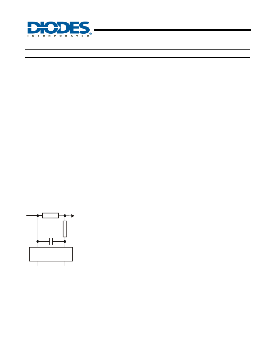
dissipation in the chip. The sense voltage can be increased further, without damaging the ZXCT1012, by the inclusion of a
resistor, R
LIM
, between SENSE- pin and the load. Typical values around 10k
Ω. See figure below.
ZXCT1012
R
SENSE
R
LIM
C
C
If large reverse currents are expected then the resistor, R
LIM
, will provide protection from exceeding absolute maximum ratings.
A suitable value for R
LIM
can be determined from:
mA
5
V
R
)
REF
(
SENSE
LIM
=
Where V
SENSE(REV)
is the maximum expected reverse sense voltage generated.