Zxct1012, Reduced height micro-power current monitor, Pin descriptions – Diodes ZXCT1012 User Manual
Page 2: Absolute maximum ratings, Recommended operating conditions
ZXCT1012
REDUCED HEIGHT MICRO-POWER CURRENT MONITOR
ZXCT1012
Document number: DS33444 Rev. 2 - 2
2 of 9
September 2011
© Diodes Incorporated
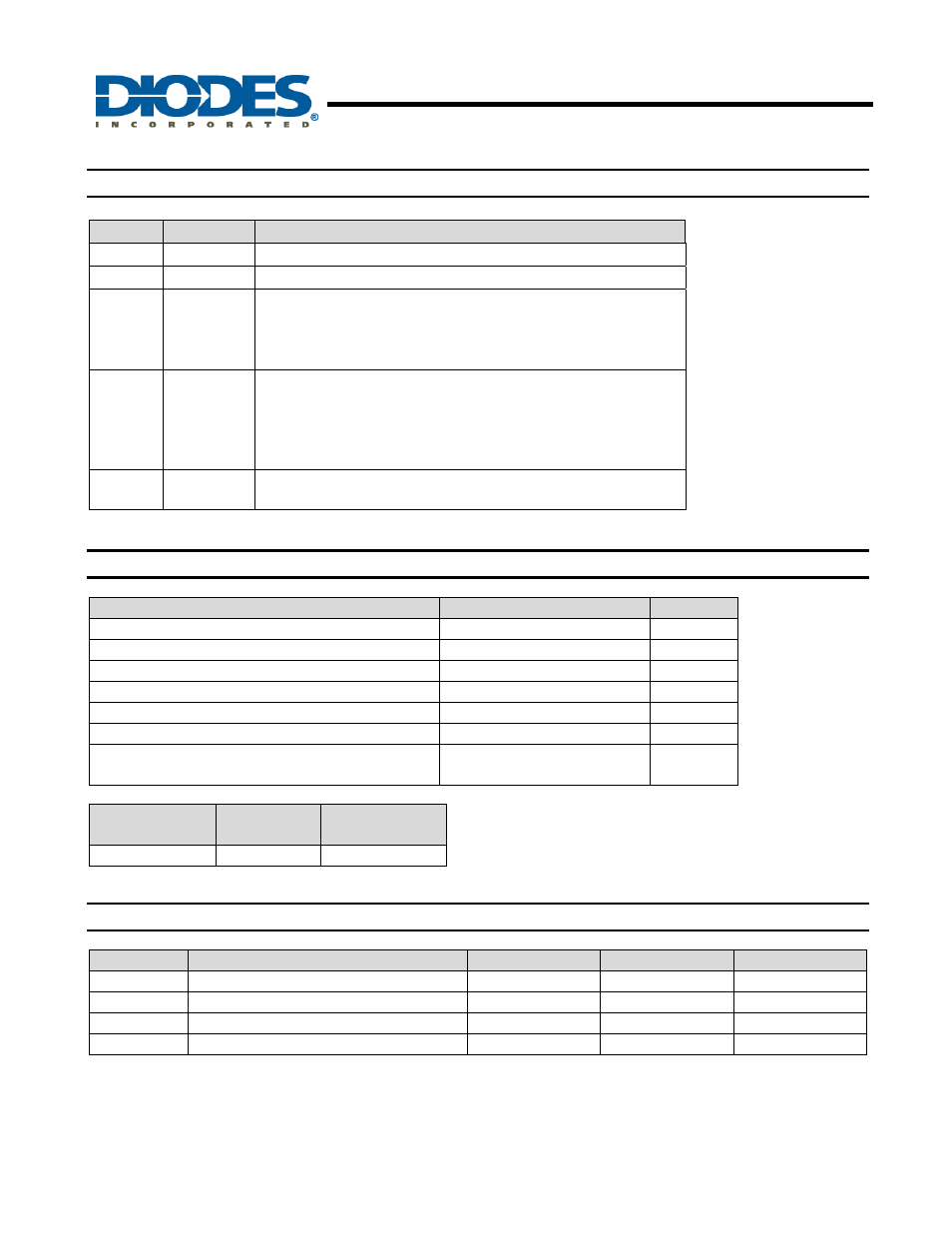
Pin Descriptions
Pin
Name
Description
1 N/C
No connection
2 GND
Ground connection
3 OUT
Output current pin. Current generated due to a difference voltage
between V
SENSE+
and V
SENSE-
flows out of this pin. A suitable
value resistor connected to ground creates an output voltage. The
maximum voltage out of this pin will be V
SENSE-
- 1.5V.
4 SENSE+
This pin should be connected to the rail whose current is being
measured and also provides power to internal circuitry. It is the
positive input of the current monitor and has an input range from
20V down to 2.5V. The current through this pin varies with
differential sense voltage.
5 SENSE-
This is the negative input of the current monitor and has an input
range from 20V down to 2.5V.
Absolute Maximum Ratings
(T
A
= 25
°C)
Description
Rating
Unit
V
SENSE+
Max. 20
V
Voltage on any pin(relative to GND pin)
-0.6 and V
SENSE+
+0.5 V
V
SENSE
(Note 1)
-0.15 to 3
V
Ambient Operating Temperature Range
-40 to 85
°C
Storage Temperature
-55 to 150
°C
Maximum Junction Temperature
150
°C
Power Dissipation (T
A
= 25°C)
300
(De-rate to 0 at 150°C)
mW
Package
(Note 2)
R
θJA
P
DISS
@ 25°C
TSOT25 250°C/W 500mW
Recommended Operating Conditions
Symbol
Parameter
Min.
Max.
Units
V
IN
Sense+
range
2.5
20
V
T
A
Ambient temperature range differential
-40
85
C
V
SENSE
Sense
voltage
10
2500
mV
V
OUT
Output voltage swing
0
V
SENSE-
-15 V
Operation above the absolute maximum rating may cause device failure.
Operation at the absolute maximum ratings, for extended periods, may reduce device reliability.
Notes: 1.
V
SENSE
is defined as the differential voltage between the SENSE+ and SENSE- pins. (V
SENSE
= V
SENSE+
- V
SENSE-
)
2. Mounted on 30mm x 16mm x1.1mm FR4 board with 1oz copper.