Zxct1012, Reduced height micro-power current monitor, Electrical characteristics – Diodes ZXCT1012 User Manual
Page 3
ZXCT1012
REDUCED HEIGHT MICRO-POWER CURRENT MONITOR
ZXCT1012
Document number: DS33444 Rev. 2 - 2
3 of 9
September 2011
© Diodes Incorporated
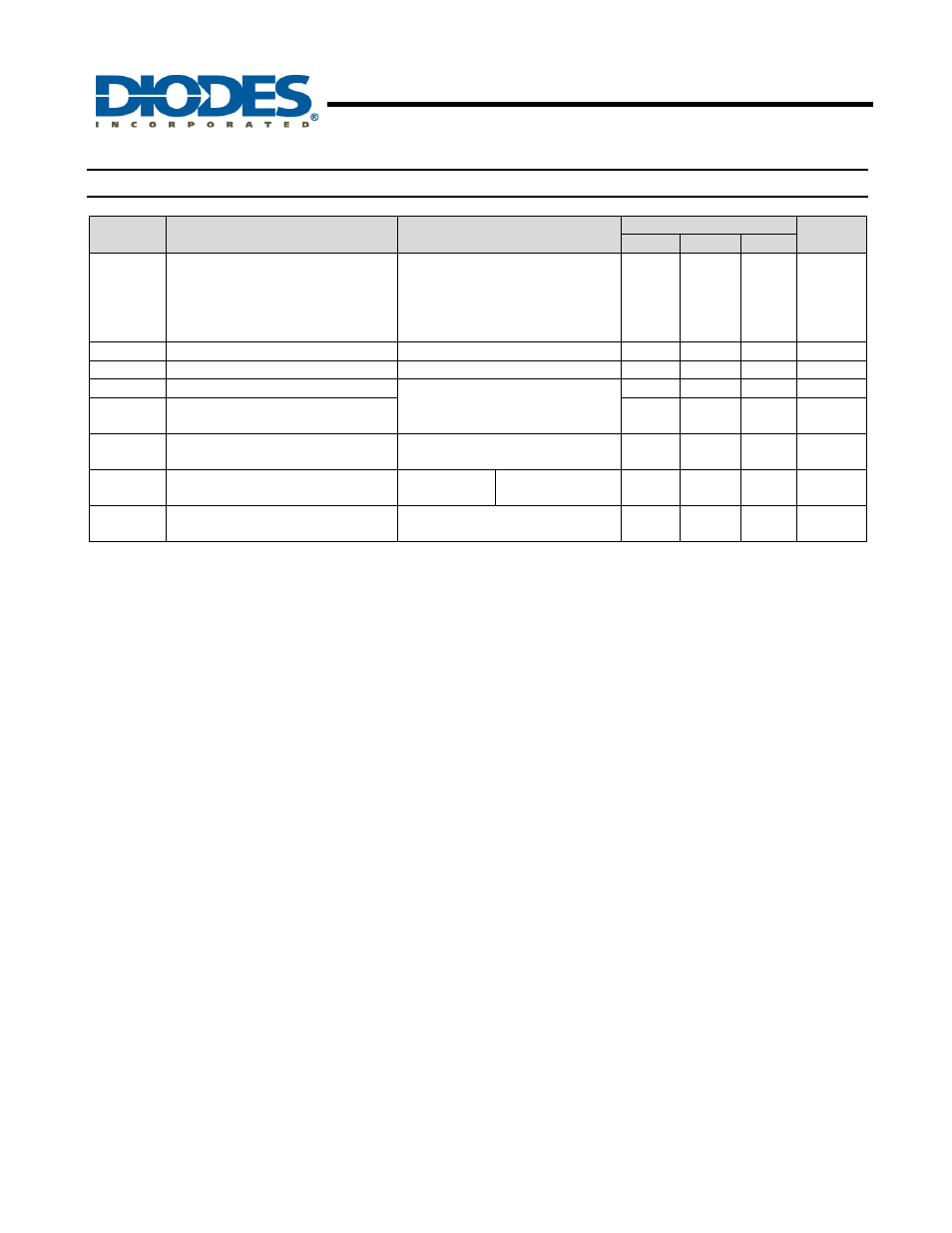
Electrical Characteristics
(T
A
= 25
°C, V
IN
= V
SENSE+
= 5V; unless otherwise specified)
Symbol
Parameter
Conditions
Limits
Unit
Min.
Typ.
Max.
I
OUT
Output
Current
V
SENSE
= 0V
V
SENSE
= 10mV
V
SENSE
= 40mV
V
SENSE
= 100mV
V
SENSE
= 200mV
0
85
380
0.975
1.95
0.3
100
400
1.00
2.00
15
115
420
1.025
2.05
µA
µA
µA
mA
mA
I
Q
Ground Pin Current
V
SENSE
= 0V
3.5
8
µA
I
SENSE-
SENSE- Pin Input Current
100
nA
A
CC
Accuracy
R
SENSE
= 0.1V
V
SENSE
= 200mV
-2.5 2.5 %
Gm
Transconductance,I
OUT
/V
SENSE
(Note 3)
10 mA/V
T
C
Temperature
Coefficient
V
SENSE
= 200mV
T
A
= 0 to 50°C (Note 3)
500
ppm/°C
BW Bandwidth
C
L
= 5pF
R
OUT
= 1k
Ω
V
SENSE
= 10mV
V
SENSE
= 100mV
300
2
kHz
MHz
CMRR
(Note 4)
Common Mode Rejection Ratio
V
SENSE
= 100mV, R
OUT
= 1k
Ω
V
IN
= 2.5V to 20V
80 dB
Notes:
3. Temperature dependent measurements are extracted from characterisation and simulation results.
4. With the ZXCT1012 using SENSE+ as its power supply pin, common mode rejection cannot be distinguished from power supply rejection.