Zxct1011 – Diodes ZXCT1011 User Manual
Page 7
ZXCT1011
© Zetex Semiconductors plc 2005
Application information (cont.)
Minimum operating voltage
The minimum operating voltage of the ZXCT1011 is 2.5V and is defined as the difference between
V
sense+
and the I
out
pin. It must be ensured that sufficient headroom is given for the operation of
the device when considering R
out
.
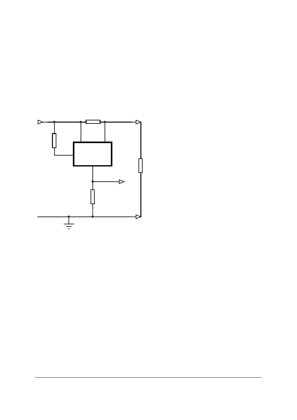
Figure 2
Considerations for supply rail
Voltage across device 2.5V
V
in
- V
out
2.5V
Where V
out
= I
out
x R
out
At low supply voltages and high Vsense measurements, special care must be taken to ensure the
correct operation.
The circuit in figure 2.0 shows a ZXCT1011 operating from 10V supply rail. The minimum
operating voltage of the ZXCT1011 is 2.5V. This allows a maximum output voltage of 7.5V to be
set at V
out
. A 3k resistor on the output would draw a maximum 2.5mA from Iout. - See minimum
usable supply voltage graph on page 4.
V
sense+
ZXCT
1011
sense-
V
V
in
R
sense
load
To
I
out
2
5
4
3.3K
V
out
R
shunt
3
R
Rshunt
120R
= 10V
- PDS3200 (5 pages)
- PDS340 (5 pages)
- PDS340Q (5 pages)
- PDS360 (5 pages)
- PDS360Q (5 pages)
- PDS4150 (4 pages)
- PDS3100Q (5 pages)
- PDS3100 (5 pages)
- PDS1240CTL (5 pages)
- PDS1045 (5 pages)
- PDS1040L (5 pages)
- PDS1040CTL (5 pages)
- PDS1040 (5 pages)
- PD3S230L (5 pages)
- PD3S230H (3 pages)
- PDS5100Q (5 pages)
- PDS835L (5 pages)
- PDS760 (5 pages)
- PDS560 (5 pages)
- PDS540 (5 pages)
- PDS5100H (5 pages)
- PDS5100 (5 pages)
- PDS4200H (6 pages)
- SBL3060CTP (4 pages)
- SBL30L30CT (3 pages)
- SBL3045CTP (4 pages)
- SBL3040CTP (4 pages)
- SBL2060CTP (4 pages)
- SBL2030CT - SBL2060CT (3 pages)
- SBL2045CTP (4 pages)
- SBL1060CTP (4 pages)
- SBL1040CTP (4 pages)
- SBG3030CT - SBG3045CT (5 pages)
- SB520 - SB560 (3 pages)
- SB370 - SB3100 (3 pages)
- SB320 - SB360 (3 pages)
- SBR10U100CT (5 pages)
- SBR10U150CT (5 pages)
- SBR10A45SP5 (5 pages)
- SBR1060CT (5 pages)
- SBR1045SP5 (5 pages)
- SBR1045SD1 (4 pages)
- SBR1045D1 (5 pages)
- SBR1045CTL (4 pages)
- SBR1040CT (5 pages)