Zxct1011, Absolute maximum ratings, Electrical characteristics – Diodes ZXCT1011 User Manual
Page 2
ZXCT1011
© Zetex Semiconductors plc 2005
Absolute maximum ratings
V
sense+
20 V
Voltage on any pin
0.6V and V
sense+
+0.5V
V
sense+
to V
sense-
2.5V
Operating temperature
-40 to 125°C
Storage temperature
-55 to 150°C
Maximum junction temperature
150°C
Package power dissipation
300mW at T
A
= 25°C (De-rate to zero at 150°C)
Operation above the absolute maximum rating may cause device failure. Operation at the
absolute maximum ratings, for extended periods, may reduce device reliability.
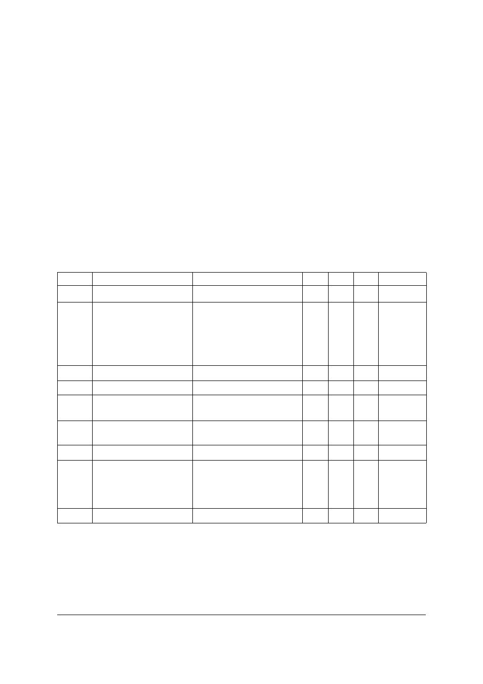
Electrical characteristics
Test conditions T
A
= 25°C, V
in
= 5V, R
shunt
= 120
⍀. V
sense
=100mV. Unless otherwise stated.
Symbol Parameter
Conditions
Min
Typ.
Max
Units
V
in
*
NOTES:
* V
sense+
relative to I
out
.
Supply range
-
2.5
-
20
V
I
out
Output current
V
sense
= 0V
=10mV
=30mV
=100mV
=200mV
=500mV
1
84
273
0.97
1.95
4.85
4
116
320
1.00
2.00
5.00
15
124
330
1.03
2.05
5.15
µA
µA
µA
mA
mA
mA
V
sense
Sense voltage
†
† V
sense
= (V
sense+
) - (V
sense-
).
-
0
-
500
mV
I
sense -
V
sense-
input current
-
-
-
100
nA
Acc
Accuracy
R
sense
= 0.1
⍀
V
sense
= 100mV
-3
-
3
%
g
m
Transconductance
I
out
/V
sense
R
shunt
= 120
⍀
-
10
-
mA/V
Tc
Temperature coefficient
‡
‡ Temperature dependent measurements are extracted from characterization and simulation results.
-
-
30
150
ppm/
° C
BW
**
** Where CL is the capacitance across R
out
.
Bandwidth
V
sense
= 10mV
CL = 5pF, R
out
= 1k
⍀
V
sense
= 100mV
CL = 5pF, R
out
= 1k
⍀
-
400
1.5
-
kHz
MHz
PSSR
Supply rejection
V
sense
= 200mV, R
out
=1k
⍀
-
68
-
dB