Zxbm2004, Two phase variable speed motor control pre-driver, New prod uc t typical application circuit – Diodes ZXBM2004 User Manual
Page 2: Pin descriptions
ZXBM2004
TWO PHASE VARIABLE SPEED
MOTOR CONTROL PRE-DRIVER
ZXBM2004
Document number: DS33433 Rev. 5 - 2
2 of 19
February 2012
© Diodes Incorporated
NEW PROD
UC
T
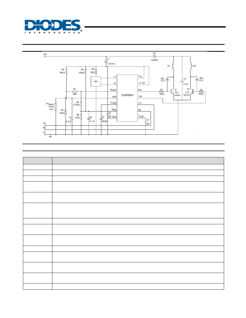
Typical Application Circuit
Pin Descriptions
Pin Name
Description
H+
Hall input to non-inverting input of internal operational amplifier
H-
Hall input to inverting input of internal operational amplifier
ThRef
Reference output voltage
SPD
Speed control pin; The control signal voltage should be between 3V to 1V for 0% to 100% (full speed)
speed control
C
PWM
PWM frequency setting pin: Connect a capacitor from this pin to ground (0V) to set PWM frequency.
Capacitor of 0.1nF will give PWM frequency of 24kHz typical.
S
MIN
Minimum speed setting pin: Voltage between 3V to 1V on this pin sets the minimum speed
between 0% to full speed. Lowest minimum speed achieved depends on the motor coil
design.
GND
Supply return ground pin
C
LCK
Rotor lock detect and auto re-start timing pin: Connect a capacitor from this pin to ground to set the lock
detect and restart timing.
RD
Rotor lock detect pin: Open collector output to indicate rotor lock detection
Connect a pull-up resistor from the pin to the pull-up supply rail
FG
Frequency Generator output to provide a tachometer signal
Ph1
Phase-1 low-side external power switch drive output pin: Darlington emitter follower output with active
pull down to give source/sink current of 80mA/16mA
Ph2
Phase-2 low-side external power switch drive output pin: Darlington emitter follower output with active
pull down to give source/sink current of 80mA/16mA
V+OP
Phase output supply voltage pin: The pin allows to optimize the supply to output drive depending on
whether external power switch is Bipolar switch or MOSFET
V
CC
Power supply pin