Zxld1370, Application information – Diodes ZXLD1370 User Manual
Page 18
ZXLD1370
Document number: DS32165 Rev. 5 - 2
18 of 39
September 2012
© Diodes Incorporated
ZXLD1370
A Product Line of
Diodes Incorporated
Application Information
(cont.)
Setting the LED current
The LED current requirement determines the choice of the sense resistor Rs. This also depends on the voltage on the ADJ pin and the voltage
on the GI pin, according to the topology required.
The ADJ pin may be connected directly to the internal 1.25V reference (V
REF
) to define the nominal 100% LED current. The ADJ pin can also be
driven with an external dc voltage between 125mV and 2.5V to adjust the LED current proportionally between 10% and 200% of the nominal
value.
For a divider ratio GI_ADJ greater than 0.65V, the ZXLD1370 operates in Buck mode when V
ADJ
= 1.25V. If GI_ADJ is less than 0.65V (typical),
the device operates in Boost or buck-Boost mode, according to the load connection. This 0.65V threshold varies in proportion to V
ADJ
, i.e., the
Buck mode threshold voltage is 0.65 V
ADJ
/1.25V.
ADJ and GI are high impedance inputs within their normal operating voltage ranges. An internal 2.6V clamp protects the device against
excessive input voltage and limits the maximum output current to approximately 4% above the maximum current set by V
REF
if the maximum
input voltage is exceeded.
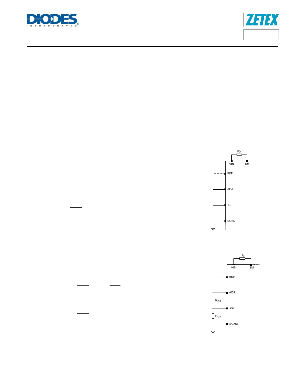
Buck Topology
In Buck mode, GI is connected to ADJ as in Figure 25. The LED current depends only
upon R
S
, V
ADJ
and V
REF
. From Equation 1 above,
⎟⎟
⎠
⎞
⎜⎜
⎝
⎛
⎟⎟
⎠
⎞
⎜⎜
⎝
⎛
=
V
V
I
218
.
0
R
REF
ADJ
LED
SBUCK
Equation 10
If ADJ is directly connected to VREF, this becomes:
⎟⎟
⎠
⎞
⎜⎜
⎝
⎛
=
I
218
.
0
R
LED
SBUCK
Figure 25 Setting LED Current in
Buck Configuration
Boost and Buck-Boost Topology
For Boost and Buck-boost topologies, the LED current depends upon the resistors, R
S
,
R
GI1
, and R
GI2
as in Equations 4 and 2 above. There is more than one degree of
freedom. That is to say, there is not a unique solution. From Equation 4,
⎟⎟
⎠
⎞
⎜⎜
⎝
⎛
⎟⎟
⎠
⎞
⎜⎜
⎝
⎛
=
V
V
ADJ
_
GI
I
225
.
0
R
REF
ADJ
LED
SBOOSTBB
Equation 11
If ADJ is connected to REF, this becomes
ADJ
_
GI
I
225
.
0
R
LED
SBOOSTBB
⎟⎟
⎠
⎞
⎜⎜
⎝
⎛
=
GI_ADJ is given by Equation 2, repeated here for convenience:
⎟
⎠
⎞
⎜
⎝
⎛
+
=
2
RGI
1
RGI
1
RGI
ADJ
_
GI
Figure 26 Setting LED Current in Boost
and Buck-Boost Configuration
Note that from considerations of ZXLD1370 input bias current, the recommended limits for R
GI1
are:
22kΩ < R
GI1
< 100kΩ
Equation 12