Zxld1321 – Diodes ZXLD1321 User Manual
Page 12
ZXLD1321
Issue 1 - January 2008
12
www.zetex.com
© Zetex Semiconductors plc 2008
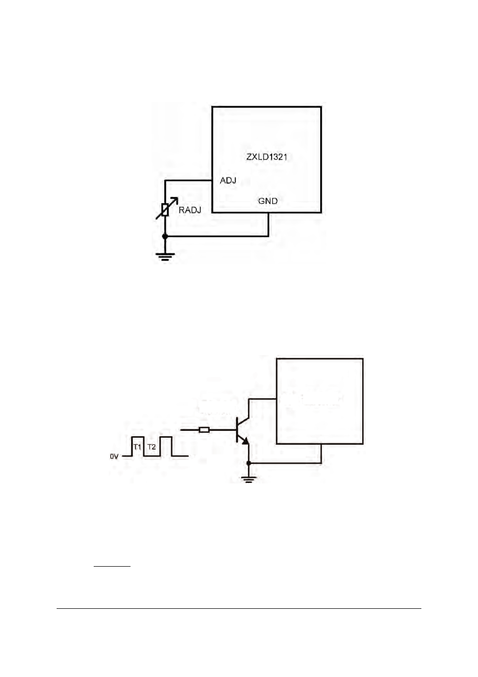
Fig 1
PWM control
A wider dimming range can be achieved by applying a PWM control signal to the ADJ pin to turn
the device on and off, giving an average output current proportional to the duty cycle of the
control signal. The ADJ pin can be driven directly from the open drain NMOS output of a
microcontroller, or indirectly with a low saturation voltage NPN transistor such as the Zetex
ZXTN25015DFH. (Fig 2).
Fig 2
In the circuit of Fig 4, the average LED output current will be
Where duty cycle
A PWM frequency of 200Hz, or lower is recommended, to minimize errors due to the rise and fall
times of the converter output.
ZXLD1321
ADJ
ZXTN25015DFH
D
nom
I
avg
I
LED
LED
*
)
(
)
(
=
)
2
1
(
2
T
T
T
D
+
=
See also other documents in the category Diodes Hardware:
- PDS3200 (5 pages)
- PDS340 (5 pages)
- PDS340Q (5 pages)
- PDS360 (5 pages)
- PDS360Q (5 pages)
- PDS4150 (4 pages)
- PDS3100Q (5 pages)
- PDS3100 (5 pages)
- PDS1240CTL (5 pages)
- PDS1045 (5 pages)
- PDS1040L (5 pages)
- PDS1040CTL (5 pages)
- PDS1040 (5 pages)
- PD3S230L (5 pages)
- PD3S230H (3 pages)
- PDS5100Q (5 pages)
- PDS835L (5 pages)
- PDS760 (5 pages)
- PDS560 (5 pages)
- PDS540 (5 pages)
- PDS5100H (5 pages)
- PDS5100 (5 pages)
- PDS4200H (6 pages)
- SBL3060CTP (4 pages)
- SBL30L30CT (3 pages)
- SBL3045CTP (4 pages)
- SBL3040CTP (4 pages)
- SBL2060CTP (4 pages)
- SBL2030CT - SBL2060CT (3 pages)
- SBL2045CTP (4 pages)
- SBL1060CTP (4 pages)
- SBL1040CTP (4 pages)
- SBG3030CT - SBG3045CT (5 pages)
- SB520 - SB560 (3 pages)
- SB370 - SB3100 (3 pages)
- SB320 - SB360 (3 pages)
- SBR10U100CT (5 pages)
- SBR10U150CT (5 pages)
- SBR10A45SP5 (5 pages)
- SBR1060CT (5 pages)
- SBR1045SP5 (5 pages)
- SBR1045SD1 (4 pages)
- SBR1045D1 (5 pages)
- SBR1045CTL (4 pages)
- SBR1040CT (5 pages)