Electrical characteristics – Diodes ZXMS6004SG User Manual
Page 5
IntelliFET
®
is a registered trademark of Diodes Incorporated
ZXMS6004SG
Document number: DS32247 Rev. 1 - 2
5 of 9
April 2014
© Diodes Incorporated
ZXMS6004SG
ADVAN
CE I
N
F
O
RM
ATI
O
N
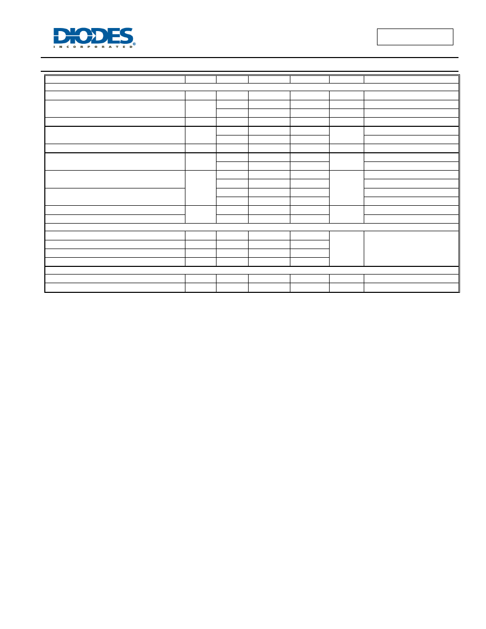
Electrical Characteristics
(@T
A
= +25°C, unless otherwise specified.)
Characteristic Symbol
Min
Typ
Max
Unit
Test
Condition
Static Characteristics
Drain-Source Clamp Voltage
V
DS(AZ)
60 65 70 V
I
D
= 10mA
Off State Drain Current
I
DSS
— — 500 nA
V
DS
= 12V, V
IN
= 0V
— — 1 µA
V
DS
= 36V, V
IN
= 0V
Input Threshold Voltage
V
IN(th)
0.7 1 1.5 V
V
DS
= V
GS
, I
D
= 1mA
Input Current
I
IN
—
60 100
A
V
IN
= +3V
—
120 200
V
IN
= +5V
Input Current While Over Temperature Active
— — — 400
A
V
IN
= +5V
Static Drain-Source On-State Resistance
R
DS(on)
—
400 600
m
V
IN
= +3V, I
D
= 0.5A
—
350 500
V
IN
= +5V, I
D
= 0.5A
Continuous Drain Current (Note 4)
I
D
0.9
— —
A
V
IN
= 3V; T
A
= 25
C
1.0
— —
V
IN
= 5V; T
A
= 25
C
Continuous Drain Current (Note 5)
1.2
— —
V
IN
= 3V; T
A
= 25
C
1.3
— —
V
IN
= 5V; T
A
= 25
C
Current Limit
I
D(LIM)
0.7 1.7 —
A
V
IN
= +3V
Current Limit (Note 7)
1
2.2
—
V
IN
= +5V
Dynamic Characteristics
Turn On Delay Time
t
d(on)
—
5
—
s
V
DD
= 12V, I
D
= 0.5A, V
GS
= 5V
Rise Time
t
r
—
10
—
Turn Off Delay Time
t
d(off)
—
45
—
Fall Time
f
f
—
15
—
Over-Temperature Protection
Thermal Overload Trip Temperature (Note 8)
T
JT
150 175 —
C
—
Thermal Hysteresis (Note 8)
f
f
— 10 —
C
—
Notes: 7. The drain current is restricted only when the device is in saturation (see graph ‘typical output characteristic’). This allows the device to be used in the fully
on state without interference from the current limit. The device is fully protected at all drain currents, as the low power dissipation generated outside
saturation makes current limit unnecessary.
8. Over-temperature protection is designed to prevent device destruction under fault conditions. Fault conditions are considered as “outside” normal
operating range, so this part is not designed to withstand over-temperature for extended periods.