Absolute maximum ratings, Thermal resistance, Zxms6004dg – Diodes ZXMS6004DG User Manual
Page 3: Absolute maximum ratings thermal resistance
ZXMS6004DG
.zetex.com
© Diodes Incorporated, 2008
www.diodes.com
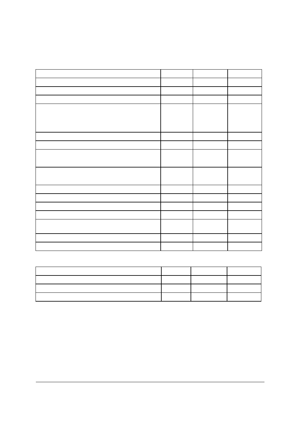
Absolute maximum ratings
Thermal resistance
NOTES
(a) For a device surface mounted on a 15mm x 15mm single sided 1oz weight copper on 1.6mm FR4 board, in still air
conditions.
(b) For a device surface mounted on 50mm x 50mm single sided 2oz weight copper on 1.6mm FR4 board in still air
conditions.
(c) Thermal resistance from junction to the mounting surface of the drain pin.
Parameter
Symbol
Limit
Unit
Continuous Drain-Source voltage
V
DS
60
V
Drain-Source voltage for short circuit protection
V
DS(SC)
36
V
Continuous input voltage
V
IN
-0.5 ... +6
V
Continuous input current
-0.2V
≤V
IN
≤6V
V
IN
<-0.2V or V
IN
>6V
I
IN
No limit
│I
IN
│≤2
mA
Operating temperature range
T
j
,
-40 to +150
°C
Storage temperature range
T
stg
-55 to +150
°C
Power dissipation at T
A
=25°C
Linear derating factor
P
D
1.3
10.4
W
mW/°C
Power dissipation at T
A
=25°C
Linear derating factor
P
D
3.0
24
W
mW/°C
Pulsed drain current @ V
IN
=3.3V
I
DM
2
A
Pulsed drain current @ V
IN
=5V
I
DM
2.5
A
Continuous source current (Body Diode)
I
S
1
A
Pulsed dource current (Body Diode)
I
SM
5
A
Unclamped single pulse inductive energy,
Tj=25°C, I
D
=0.5A, V
DD
=24V
E
AS
490
mJ
Electrostatic discharge (Human body model)
V
ESD
4000
V
Charged device model
V
CDM
1000
V
Parameter
Symbo
Value
Unit
Junction to ambient
R
θJA
96
°C/W
Junction to ambient
R
θJA
42
°C/W
Junction to case
R
θJC
12
°C/W