Zxsbmr16pt8, Maximum ratings, Thermal characteristics – Diodes ZXSBMR16PT8 User Manual
Page 2
ZXSBMR16PT8
Document number: DS33612 Rev. 2 - 2
2 of 6
February 2011
© Diodes Incorporated
ZXSBMR16PT8
Maximum Ratings
@T
A
= 25°C unless otherwise specified
Characteristic Symbol
Value
Units
Maximum Repetitive Reverse Voltage
V
RRM
40 V
Maximum RMS Bridge Input Voltage
V
RMS
13.2 V
Average Rectified Forward Current (Notes 2 & 3)
I
F(AV)
0.4 A
Peak Repetitive Forward Current
I
FPK
3.5 A
Non Repetitive Forward Current
t
≤ 100μs
I
FSM
13 A
t
≤ 10ms
3.5 A
Thermal Characteristics
Characteristic Symbol
Value
Unit
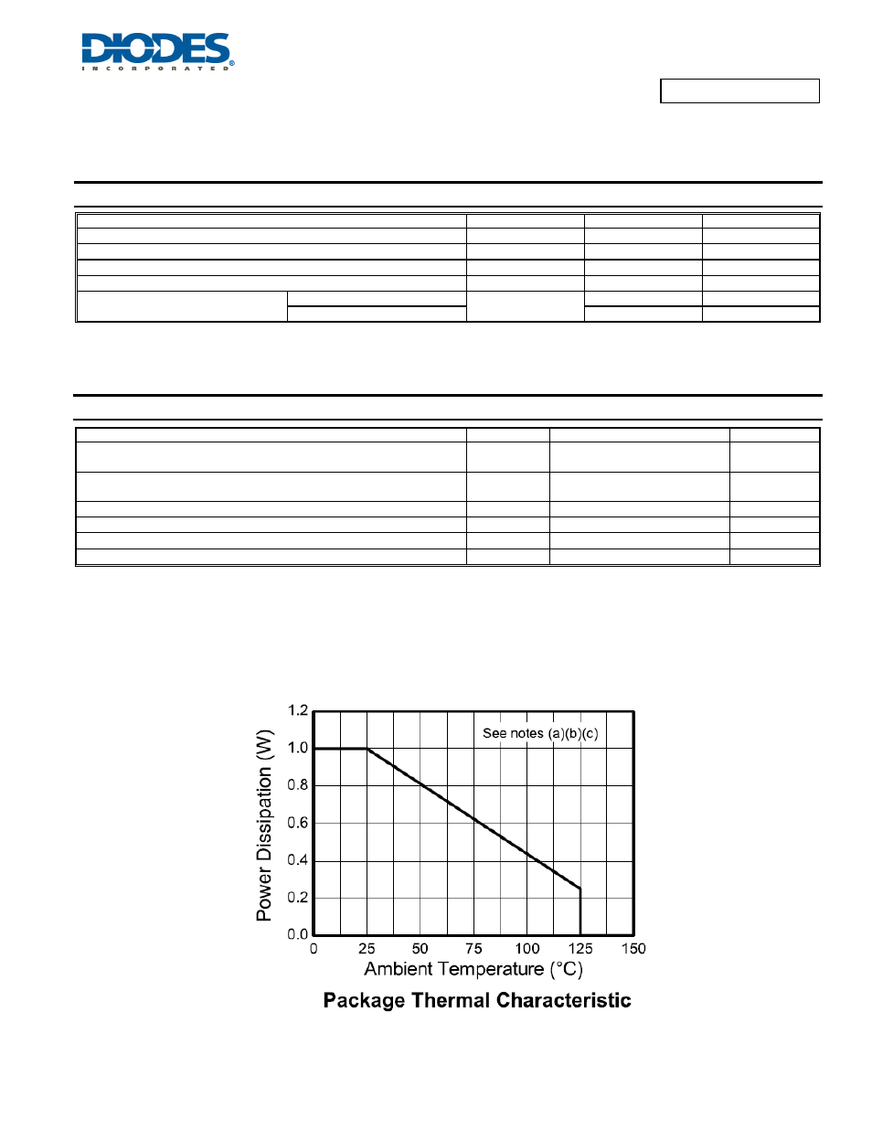
Power Dissipation, T
A
= 25°C (Note 2)
P
D
1 W
Thermal Resistance, Junction to Ambient (Note 2)
R
θJA
125 °C/W
Junction Temperature, Forward Dissipation Only
T
J
150 °C
Junction Temperature, Reverse Dissipation (Notes 2, 3, & 4)
T
J
125 °C
Storage Temperature Range
T
STG
-55 to +150
°C
MR16 LED Internal Ambient Temperature (Note 4)
T
A
90 °C
Notes:
2. For a bridge mounted on1.6mm FR4 PCB with minimum copper pads and track dimensions in still air.
3.
Supply 12V RMS with capacitive bridge load.
4. Maximum bridge operating junction temperature must be reduced with increased reverse bias voltage to maintain unconditional thermal stability.
5. Refer to Design Note DN86