AVSL Citronic CLA-300 User Manual
Page 5
171.227, 171.228 User Manual
Installation
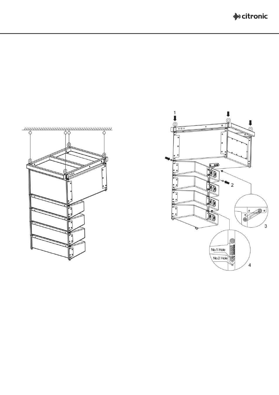
Single Flown Array
For standard single flown array, installation is executed using 4 supplied eyebolts attached to each
corner of the flying frame. Fixings should be the strongest possible type for the substrate or ceiling
supports to ensure a fail-safe installation. Suspension via wire rope or steel cables, each with a
breaking strain of no less than 200kg is recommended per single line-array system.
In some situations, it may be easier to suspend the sub unit first and then assemble line-array
speakers below it, ensuring that the weight of each is adequately supported before securing to the
array.
Once assembled, the line-array can be curved to
address the listening field by selecting various angle points on the Passive Back Link brackets
provided. The angle chosen depends largely upon the distance from the audience and the acoustic
environment but should be adjusted so that each array speaker unit is vertically focused to evenly
distribute the output across the listening field.
Each Passive Back Link bracket has numbered lines for tilt in degrees. Number 1 Hole is used for
even number degrees tilt and Number 2 Hole is used for odd number degrees of tilt. Whilst
supporting the weight of the passive speaker, use these lines to align the correct fastening hole for
the degree of tilt required for each component in the array.
For example, if the required splay angle is 5
, the line marked with the number 5 on the Passive Back
Link must be aligned with the bottom edge of the groove on the back of the top speaker. The
Number 2 Hole on the lower speaker can aligned with the hole in the Passive Back Link and secured
using the M5 screw.