6 maintenance, Sensor replacement – Analytical Industries GPR-2500 Series Oxygen Transmitter User Manual
Page 32
32
6 Maintenance
Generally, cleaning the electrical contacts or replacing filter elements is the extent of the maintenance
requirements of this transmitter.
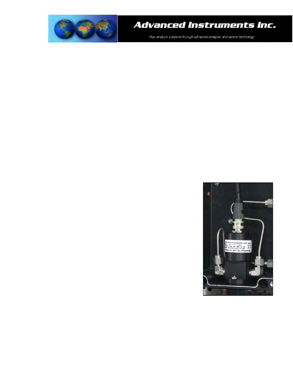
Sensor Replacement
Periodically, the oxygen sensor will require replacement. The operating life is determined by a number of factors
that are influenced by the user and therefore difficult to predict. The Features & Specifications define the normal
operating conditions and expected life of the standard sensor utilized by the GPR-2500/2500MO transmitter.
Expected sensor life is inversely proportional to changes in oxygen concentration, pressure and temperature.
Serviceability: Except for replacing the oxygen sensor, there are no parts inside the transmitter for the operator
to service. Only trained personnel with the authorization of their supervisor should conduct maintenance.
Caution: DO NOT open the oxygen sensor. The sensor contains a corrosive liquid electrolyte that could be harmful
if touched or ingested, refer to the Material Safety Data Sheet contained in the Owner’s Manual. Avoid contact with
any liquid or crystal type powder in or around the sensor or sensor housing, as either could be a form of
electrolyte. Leaking sensors should be disposed of in accordance with local regulations.
Procedure:
1. Remove the four (4) screws securing the hinged front panel of the transmitter
and raise it up 180º until it locks into position.
2. Caution: Do not remove or discard the gaskets from the enclosure. Failure to
reinstall the gasket will void the NEMA rating.
3. Unscrew the knurled lock nut connecting the cable to the sensor.
4. Disconnect and remove the female plug (including the knurled lock nut)
molded to the cable from the male receptacle attached to the sensor.
5. Unscrew the old sensor from the threaded hole in the sensor flow housing.
6. Open the barrier bag containing the new sensor.
7. If the sensor is equipped with a shorting loop, remove the shorting wire from
the pins of the female socket attached to the new sensor.
8. Screw the new sensor, finger tight plus 1/2 turn, into the threaded hole in the
flow housing and ensure the o-ring seal is engaged.
9. Assure the keyway registration of the female plug on the cable and male
receptacle on the sensor match up.
10. Push the female plug (including the knurled lock nut) molded to the cable into
the male receptacle attached to the new sensor.
11. Screw and tighten the knurled lock nut attached the cable onto to the male connector attached to the sensor.
12. Replace the front cover of the transmitter, replace the gasket to maintain CE approval and NEMA 4 rating and
tighten the four (4) screws to secure the front cover.
13. Calibrate the transmitter as described in section 5.