Analytical Industries GPR-2500 Series Oxygen Transmitter User Manual
Page 18
18
10. Replace the front cover of the transmitter and ensure that the gasket is replaced as well to maintain CE
approval and NEMA 4 rating.
11. Tighten the four (4) screws to secure the front cover.
12. Connect the gas lines, vent line first, as previously described.
13. Proceed to calibration.
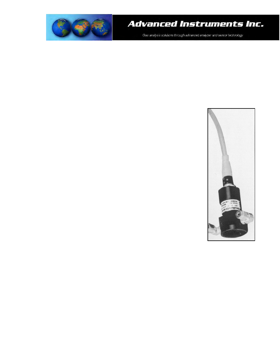
Remote Oxygen Sensor:
Applications requiring the sensor to be located remotely from the electronics dictate the
separate packaging and shipment of the electronics enclosure, oxygen sensor and
sensor flow housing. The appropriate length of cable to connect the sensor to the
electronics is supplied and connected to the electronics. To install the remote sensor:
1. Locate the sensor flow housing and note the through holes in the flanged sections.
2. Identify the spot for installation.
3. Using two (2) 6/32 screws of the appropriate type and length secure the sensor flow
housing to a flat surface, the position illustrated at the right is recommended for
optimum performance.
4. Remove the oxygen sensor from the bag.
5. Screw the oxygen sensor into the sensor flow housing, equipped with elbows and
tubing, finger tighten plus one half (1/2) turn to ensure a good seal from the o-ring
affixed to the sensor.
6. Remove the shorting device (looped wire) from the receptacle located at the rear of
the sensor. Minimize the time the sensor is exposed to ambient air.
7. Assure the keyway registration of the female plug on the cable and male receptacle
on the sensor match up.
8. Push the female plug (including the knurled lock nut) molded to the cable into the
male receptacle attached to the new sensor.
9. Screw the knurled lock nut attached the cable onto to the male connector attached
to the sensor, tighten finger tight plus ¼ turn.
10. Connect the 1/8” diameter gas lines, vent line first, as previously described.
11. Proceed to calibration.