Analytical Industries GPR-2500 Series Oxygen Transmitter User Manual
Page 15
15
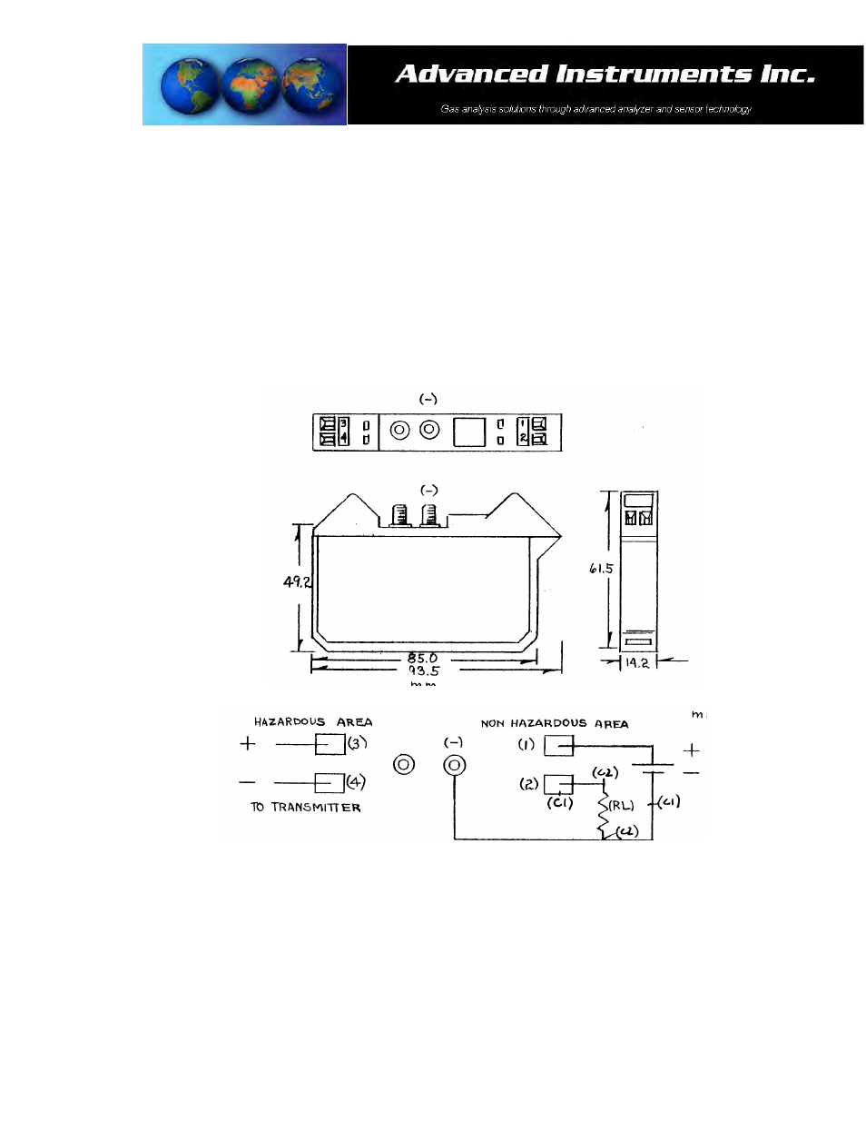
Connections – Optional Intrinsic Safety Barrier:
1. Non-hazardous area: Barrier terminals (1), (2)
2. Hazardous area: Barrier terminals (3), (4)
3. Direct measurement of 4-20mA: Reference (C1), connect the current measuring device at terminal (2) of the
barrier and the negative (-) terminal from the power source as shown below.
4. Convert 4-20mA current to voltage: Reference (C2), connect a resistor (RL) maximum value 850Ω between
terminal (2) of the barrier and the negative (-) terminal from the power source and measure the voltage across
the resistor.
5. Example: To convert the 4-20mA current for output to a PLC requiring 1-5V, follow the above procedure using
a 250Ω resistor (RL).
Hazardous Area Operation:
When used in conjunction with the optional MTL 702, third party certified, intrinsic safety barriers, the design of
the GPR-1500/2500 Series Oxygen Transmitters meet recognized standards as intrinsically safe for operation in
Class I, II, III; Division I, II; Groups A-G hazardous areas.
Note: Locate the optional intrinsic safety barrier as close to the power source in the non-hazardous area as
possible.