Iii. installation – Asus P2L97-DS User Manual
Page 29
ASUS P2L97-DS User’s Manual
29
III. INSTALLATION
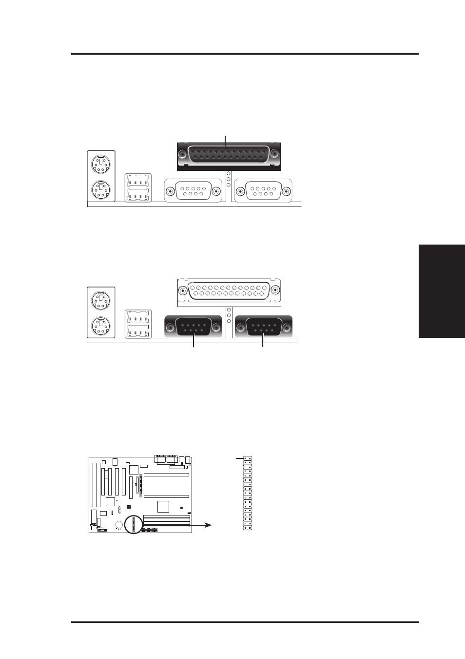
3. Parallel Printer Connector (25-pin Female)
You can enable the parallel port and choose the IRQ through “Onboard Parallel
Port” in Chipset Features Setup of the BIOS SOFTWARE. NOTE: Serial print-
ers must be connected to the serial port.
Parallel (Printer) Port (25-pin Female)
4. Serial Port COM1 and COM2 Connectors (Two 9-pin Male)
The two serial ports can be used for pointing devices or other serial devices. See
“Onboard Serial Port...” in Chipset Features Setup of the BIOS SOFTWARE.
COM 1
COM 2
Serial Ports (9-pin Male)
5. Floppy Disk Drive Connector (34-1pin FLOPPY)
This connector supports the provided floppy disk drive ribbon cable. After con-
necting the single end to the board, connect the two plugs on the other end to the
floppy drives. (Pin 5 is removed to prevent inserting in the wrong orienta-
tion when using ribbon cables with pin 5 plugged).
Pin 1
Floppy Disk Drive Connector
NOTE: Orient the
red stripe to Pin 1
R
Connectors
III. INST
ALLA
TION
- P5B Premium Vista Edition (188 pages)
- P5B (140 pages)
- P5B (56 pages)
- P5KPL-VM/1394/SI (94 pages)
- M2N68-CM (28 pages)
- P5AD2-E Premium (2 pages)
- P5GD1-VM (88 pages)
- P5AD2 Premium (8 pages)
- P5GD1-VM (92 pages)
- DELUXE A7N8X-E (114 pages)
- P5KPL-AM SE (40 pages)
- P5KPL-AM SE (38 pages)
- P5KPL-AM SE (62 pages)
- P4S8X-X (64 pages)
- P5K-VM (98 pages)
- K8V-X SE (82 pages)
- M2N68-AM SE2 (40 pages)
- P4P800 SE (125 pages)
- P4P800 SE (16 pages)
- DELUXE SERIES M3A32-MVP (176 pages)
- P5AD2 Deluxe (148 pages)
- M4A79 Deluxe (122 pages)
- A7V266-E (108 pages)
- Application Manual (8 pages)
- Application Manual (2 pages)
- Application Manual (6 pages)
- Application Manual (9 pages)
- Application Manual (3 pages)
- Application Manual (1 page)
- Application Manual (5 pages)
- Application Manual (11 pages)
- Application Manual (10 pages)
- Application Manual (4 pages)
- M4A88T-I DELUXE (70 pages)
- M4A88T-I DELUXE (44 pages)
- P9X79 DELUXE (2 pages)
- RAMPAGE IV GENE (1 page)
- P9X79 (156 pages)
- P8H61-M PLUS V3 (64 pages)
- A85XM-A (78 pages)
- M4A78L-M LE (64 pages)
- M2N68-AM (62 pages)
- M2N68-AM (38 pages)
- M2N68-AM (96 pages)
- Blitz Formula (1 page)