Iii. installation – Asus P2L97-DS User Manual
Page 19
ASUS P2L97-DS User’s Manual
19
Install memory in any combination as follows:
DIMM Location
168-pin DIMM Memory Modules
Total Memory
Socket 0 (Rows 0&1) SDRAM/EDO 8, 16, 32, 64, 128, 256MB x1
Socket 1 (Rows 2&3) SDRAM/EDO 8, 16, 32, 64, 128, 256MB x1
Socket 2 (Rows 4&5) SDRAM/EDO 8, 16, 32, 64, 128, 256MB x1
Socket 3 (Rows 6&7) SDRAM/EDO 8, 16, 32, 64, 128, 256MB x1
Total System Memory (Max 1GB)
=
2. System Memory (DIMM)
This motherboard uses only Dual Inline Memory Modules (DIMMs). Four sockets
are available for 3.3Volt (power level) unbuffered Synchronous Dynamic Random
Access Memory (SDRAM) of either 8, 16, 32, 64, or 128MB to form a memory size
between 8MB to 512MB or Extended Data Output (EDO) DRAM of either 8, 16,
32, 64, 128, or 256MB to form a memory size between 8MB to 1GB. One side (with
memory chips) of the DIMM takes up one row on the motherboard.
To utilize the chipset’s Error Checking and Correction (ECC) feature, you must use a
DIMM module with 9 chips per side (standard 8 chips/side + 1 ECC chip) and make
the proper settings through “Chipset Features Setup” in IV. BIOS SOFTWARE.
Memory speed setup is recommended through EDO Auto Configuration under
“Chipset Features Setup”.
General DIMM Notes (not true for all memory modules)
• Four possible memory chips are supported: EDO or SDRAM with and without ECC.
• SDRAM chips are generally thinner with higher pin density than EDO chips.
• BIOS shows EDO or SDRAM memory on bootup screen.
• 8 chip/side modules do not support ECC, only 9 chip/side modules support ECC.
• Single sided modules are usually 16, 32, 64 or 128 MB, double sided are usually 8, 32, 64,
128 or 256MB.
III. INSTALLATION
III. INST
ALLA
TION
System Memory
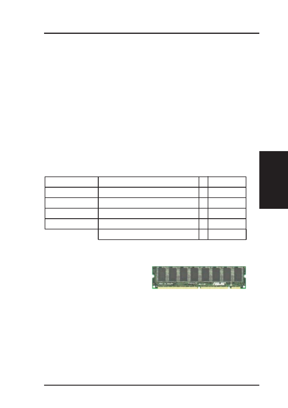
Non-ECC SDRAM DIMM (8 chips)
ASUS Memory Modules
ECC EDO DIMM (9 chips)