22 chapter 1: product introduction – Asus P4S800D User Manual
Page 32
1-22
Chapter 1: Product introduction
P4S800D
®
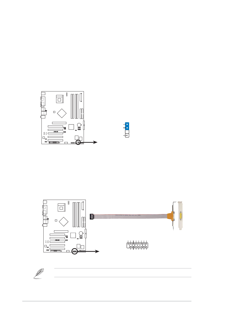
P4S800D Chassis Alarm Lead
CHASSIS1
+5VSB_MB
Chassis Signal
GND
(Default)
P4S800D
®
P4S800D Game Connector
GAME1
+5V
+5V
J2B1
J2CX
MIDI_OUT
J2CY
J2B2
MIDI_IN
J1B1
J1CX
GND
GND
J1CY
J1B2
+5V
10. GAME/MIDI connector (16-1 pin GAME1)
This connector supports a GAME/MIDI module. If a GAME/MIDI module is
available, connect the GAME/MIDI cable to this connector. The GAME/MIDI
port on the module connects a joystick or a game pad for playing games, and
MIDI devices for playing or editing audio files.
9. Chassis intrusion connector (4-1 pin CHASSIS1)
This lead is for a chassis designed with intrusion detection feature.
This requires an external detection mechanism such as a chassis
intrusion sensor or microswitch. When you remove any chassis
component, the sensor triggers and sends a high-level signal to this
lead to record a chassis intrusion event.
By default, the pins labeled “Chassis Signal” and “Ground” are shorted
with a jumper cap. If you wish to use the chassis intrusion detection
feature, remove the jumper cap from the pins.
The GAME/MIDI module is purchased separately.