Asus P4S800D User Manual
Page 31
ASUS P4S800D motherboard user guide
1-21
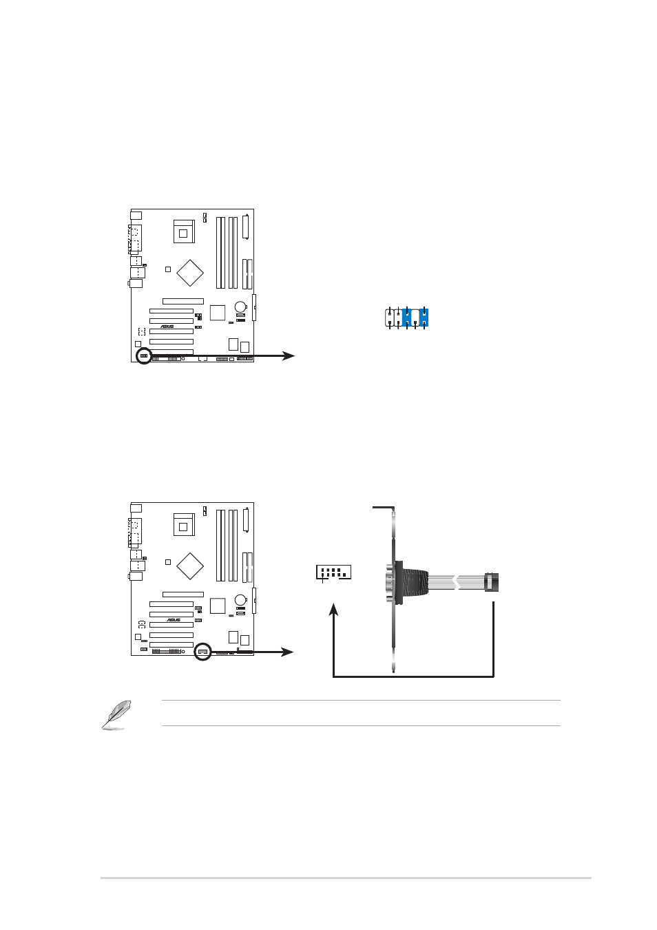
8. Serial port connector (10-1 pin COM1)
This green connector accommodates the bundled serial port module. Install
the module into a slot opening at the back of the system chassis, the connect
the module’s green cable plug to this connector.
7. Front panel audio connector (10-1 pin FP_AUDIO1)
This is an interface for the front panel cable that allows convenient connection
and control of audio devices.
Be default, the pins labeled LINE OUT_R/BLINE_OUT_R and the pins
LINE OUT_L/BLINE_OUT_L are shorted with jumper caps. Remove the caps
only when you are connecting the front panel audio cable.
P4S800D
®
P4S800D Front Panel Audio Connector
FP_AUDIO1
BLINE_OUT_L
MIC2
Line out_R
Line out_L
BLINE_OUT_R
NC
MICPWR
+5V
A
AGND
P4S800D
®
P4S800D Serial COM2 Bracket
PIN 1
COM2
The Serial COM2 bracket is purchased separately.
- P5B (140 pages)
- P5B (56 pages)
- P5B Premium Vista Edition (188 pages)
- P5KPL-VM/1394/SI (94 pages)
- M2N68-CM (28 pages)
- P5AD2 Premium (8 pages)
- P5GD1-VM (92 pages)
- P5AD2-E Premium (2 pages)
- P5GD1-VM (88 pages)
- DELUXE A7N8X-E (114 pages)
- P5KPL-AM SE (40 pages)
- P5KPL-AM SE (38 pages)
- P5KPL-AM SE (62 pages)
- P4S8X-X (64 pages)
- P5K-VM (98 pages)
- K8V-X SE (82 pages)
- M2N68-AM SE2 (40 pages)
- P4P800 SE (125 pages)
- P4P800 SE (16 pages)
- DELUXE SERIES M3A32-MVP (176 pages)
- P5AD2 Deluxe (148 pages)
- M4A79 Deluxe (122 pages)
- A7V266-E (108 pages)
- Application Manual (6 pages)
- Application Manual (9 pages)
- Application Manual (3 pages)
- Application Manual (1 page)
- Application Manual (5 pages)
- Application Manual (11 pages)
- Application Manual (10 pages)
- Application Manual (4 pages)
- Application Manual (8 pages)
- Application Manual (2 pages)
- M4A88T-I DELUXE (70 pages)
- M4A88T-I DELUXE (44 pages)
- P9X79 (156 pages)
- P9X79 DELUXE (2 pages)
- RAMPAGE IV GENE (1 page)
- P8H61-M PLUS V3 (64 pages)
- A85XM-A (78 pages)
- M4A78L-M LE (64 pages)
- M2N68-AM (38 pages)
- M2N68-AM (96 pages)
- M2N68-AM (62 pages)
- Blitz Extreme (188 pages)