Iii. hardware setup – Asus MEL-B User Manual
Page 30
30
ASUS MEL-B User’s Manual
III. HARDWARE SETUP
Connectors
III. H/W SETUP
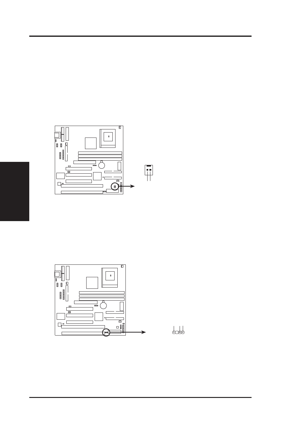
22. Wake-On-Ring Header (2-pin WOR)
This connector connects to internal modem cards with a Wake-On-Ring output.
The connector powers up the system when a ringup packet or signal is received
through the internal modem card. NOTE: For external modems, Wake-On-Ring
is detected through the COM port.
IMPORTANT: This feature requires that PWR UP On Modem Act Power Up Con-
trol is set to Enabled (see Power Management Setup under BIOS SETUP) and that your
system has an ATX power supply with at least 720mA +5V standby power.
MEL-B Wake-On-Ring Header
WOR
Pin 1 PIXRI#
Pin 2 Ground
23. Chassis Intrusion Sensor Lead (4-1 pin CHASIS)
This lead is for a chassis intrusion monitor or sensor. The sensor is triggered
when a high level signal is sent to the “chassis signal” lead. This occurs when a
panel switch or light detector is triggered. This function requires the optional
ASUS CIDB Chassis Sensor to be installed.
MEL-B Chassis Open Alarm Lead
Battery
Ground
Chassis Signal