Iii. installation, Asus sp97-xv motherboard layout, 10 asus sp97-xv user’s manual – Asus SP97-XV User Manual
Page 10: Motherboard layout) iii. inst alla tion, Multi i/o chip
10
ASUS SP97-XV User’s Manual
III. INSTALLATION
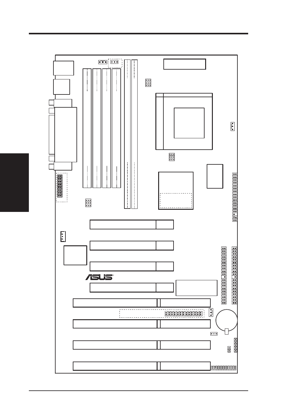
ASUS SP97-XV Motherboard Layout
Board Power Input
for ATX Power Supply
CPU ZIF Socket 7
SiS 5582
Chipset
or
SiS 5598
Chipset
VGA
Connector
ISA Slot 4
ISA Slot 1
ISA Slot 3
ISA Slot 2
R
PCI Slot 1
PCI Slot 3
PCI Slot 4
PCI Slot 2
DIMM Socket 2 (64-bit, 168-pin module)
DIMM Socket 1 (64-bit, 168-pin module)
3 2 1 0
Row
USB
PS/2
USB 1(TOP PORT)
USB 2 (BOTTOM)
MOUSE (TOP PORT)
KEYBOARD (BOTTOM)
COM 2
COM 1
P
ARALLEL
PORT
Flash EEPROM
(Programable BIOS)
Floppy Drives
CMOS Power
CR2032
3 Volt Cell
RTCLR
VGA Feature Conn.
Panel Conn.
SIMM Socket 1 (32-bit, 72-pin module)
SIMM Socket 2 (32-bit, 72-pin module)
SIMM Socket 3 (32-bit, 72-pin module)
SIMM Socket 4 (32-bit, 72-pin module)
3 2
1 0 1 0
Row
3 2
SIMM Socket 4 (32 bit, 72 pin module)
SIMM Socket 1 (32 bit, 72 pin module)
SIMM Socket 2 (32 bit, 72 pin module)
SIMM Socket 3 (32 bit, 72 pin module)
VID0
VID1
VID2
CPU Voltage
BF0
BF1
BF2
BUS Freq.
VGA_SEL
FS0
FS1
FS2
BUS Ratio
512KB Pipelined
Burst L2 Cache
IrDA
Wake on LAN
IDE LED
Multi
I/O Chip
CPU_FAN
PWR_FAN
Secondary IDE
Primary IDE
CHA_FAN
NOTE: Outlined components are available only with the onboard VGA version.
(Motherboard Layout)
III. INST
ALLA
TION