Audio 2, 4, 6, or 8-channel configuration, Wireless lan led indications – Asus P5AD2-E Premium User Manual
Page 45
A S U S P 5 A D 2 - E P r e m i u m
A S U S P 5 A D 2 - E P r e m i u m
A S U S P 5 A D 2 - E P r e m i u m
A S U S P 5 A D 2 - E P r e m i u m
A S U S P 5 A D 2 - E P r e m i u m
2 - 2 3
2 - 2 3
2 - 2 3
2 - 2 3
2 - 2 3
1 2 .
1 2 .
1 2 .
1 2 .
1 2 . U S B 2 . 0 p o r t s 3 a n d 4 .
U S B 2 . 0 p o r t s 3 a n d 4 .
U S B 2 . 0 p o r t s 3 a n d 4 .
U S B 2 . 0 p o r t s 3 a n d 4 .
U S B 2 . 0 p o r t s 3 a n d 4 . These two 4-pin Universal Serial Bus
(USB) ports are available for connecting USB 2.0 devices.
1 3 .
1 3 .
1 3 .
1 3 .
1 3 . U S B 2 . 0 p o r t s 1 a n d 2 .
U S B 2 . 0 p o r t s 1 a n d 2 .
U S B 2 . 0 p o r t s 1 a n d 2 .
U S B 2 . 0 p o r t s 1 a n d 2 .
U S B 2 . 0 p o r t s 1 a n d 2 . These two 4-pin Universal Serial Bus
(USB) ports are available for connecting USB 2.0 devices.
1 4 .
1 4 .
1 4 .
1 4 .
1 4 . O p t i c a l S / P D I F O u t p o r t
O p t i c a l S / P D I F O u t p o r t
O p t i c a l S / P D I F O u t p o r t
O p t i c a l S / P D I F O u t p o r t
O p t i c a l S / P D I F O u t p o r t. This port connects an external audio
output device via an optical S/PDIF cable.
1 5 .
1 5 .
1 5 .
1 5 .
1 5 . C o a x i a l S / P D I F O u t p o r t .
C o a x i a l S / P D I F O u t p o r t .
C o a x i a l S / P D I F O u t p o r t .
C o a x i a l S / P D I F O u t p o r t .
C o a x i a l S / P D I F O u t p o r t . This port connects an external audio
output device via a coaxial S/PDIF cable.
1 6 .
1 6 .
1 6 .
1 6 .
1 6 . P S / 2 k e y b o a r d p o r t ( p u r p l e ) .
P S / 2 k e y b o a r d p o r t ( p u r p l e ) .
P S / 2 k e y b o a r d p o r t ( p u r p l e ) .
P S / 2 k e y b o a r d p o r t ( p u r p l e ) .
P S / 2 k e y b o a r d p o r t ( p u r p l e ) . This port is for a PS/2 keyboard.
1 7 .
1 7 .
1 7 .
1 7 .
1 7 . P S / 2 m o u s e p o r t ( g r e e n ) .
P S / 2 m o u s e p o r t ( g r e e n ) .
P S / 2 m o u s e p o r t ( g r e e n ) .
P S / 2 m o u s e p o r t ( g r e e n ) .
P S / 2 m o u s e p o r t ( g r e e n ) . This port is for a PS/2 mouse.
8 .
8 .
8 .
8 .
8 .
W i r e l e s s L A N a n t e n n a p o r t
W i r e l e s s L A N a n t e n n a p o r t
W i r e l e s s L A N a n t e n n a p o r t
W i r e l e s s L A N a n t e n n a p o r t
W i r e l e s s L A N a n t e n n a p o r t (Wireless Edition only)..... This port
connects to the optional dipolar antenna for the onboard WiFi-g™
wireless LAN solution.
9 .
9 .
9 .
9 .
9 .
W i r e l e s s L A N L E D
W i r e l e s s L A N L E D
W i r e l e s s L A N L E D
W i r e l e s s L A N L E D
W i r e l e s s L A N L E D (Wireless Edition only).
.
.
.
. This green A I R
A I R
A I R
A I R
A I R LED
indicates the data transmission status of the onboard wireless LAN
adapter. Refer to the table below for the LED indications.
1 0 .
1 0 .
1 0 .
1 0 .
1 0 . M i c r o p h o n e p o r t ( p i n k ) .
M i c r o p h o n e p o r t ( p i n k ) .
M i c r o p h o n e p o r t ( p i n k ) .
M i c r o p h o n e p o r t ( p i n k ) .
M i c r o p h o n e p o r t ( p i n k ) . This port connects a microphone.
1 1 .
1 1 .
1 1 .
1 1 .
1 1 . Center/Subwoofer port (yellow orange).
C e n t e r / S u b w o o f e r p o r t ( y e l l o w o r a n g e ) .
C e n t e r / S u b w o o f e r p o r t ( y e l l o w o r a n g e ) .
C e n t e r / S u b w o o f e r p o r t ( y e l l o w o r a n g e ) .
C e n t e r / S u b w o o f e r p o r t ( y e l l o w o r a n g e ) . This port connects
the center/subwoofer speakers.
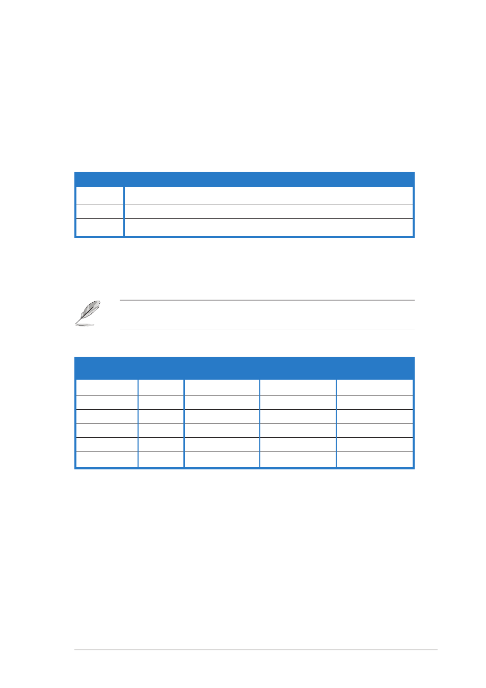
S t a t u s
S t a t u s
S t a t u s
S t a t u s
S t a t u s
I n d i c a t i o n
I n d i c a t i o n
I n d i c a t i o n
I n d i c a t i o n
I n d i c a t i o n
O n
O n
O n
O n
O n
The onboard WiFi-g™ is on but has no data activity.
O f f
O f f
O f f
O f f
O f f
The onboard WiFi-g™ is off.
F l a s h i n g
F l a s h i n g
F l a s h i n g
F l a s h i n g
F l a s h i n g The onboard WiFi-g™ is transmitting and/or receiving data.
Audio 2, 4, 6, or 8-channel configuration
Audio 2, 4, 6, or 8-channel configuration
Audio 2, 4, 6, or 8-channel configuration
Audio 2, 4, 6, or 8-channel configuration
Audio 2, 4, 6, or 8-channel configuration
Light Blue
Light Blue
Light Blue
Light Blue
Light Blue
Line In
Line In
Line In
Line In
L i m e
L i m e
L i m e
L i m e
L i m e
Line Out
Front Speaker Out Front Speaker Out
Front Speaker Out
P i n k
P i n k
P i n k
P i n k
P i n k
Mic In
Mic In
Mic In
Mic In
G r a y
G r a y
G r a y
G r a y
G r a y
—
Rear Speaker Out
Rear Speaker Out
Rear Speaker Out
B l a c k
B l a c k
B l a c k
B l a c k
B l a c k
—
—
—
Side Speaker Out
Yellow Orange
Yellow Orange
Yellow Orange
Yellow Orange
Yellow Orange
—
—
Center/Subwoofer Center/Subwoofer
P o r t
P o r t
P o r t
P o r t
P o r t
2 - c h a n n e l
2 - c h a n n e l
2 - c h a n n e l
2 - c h a n n e l
2 - c h a n n e l
4 - c h a n n e l
4 - c h a n n e l
4 - c h a n n e l
4 - c h a n n e l
4 - c h a n n e l
6 - c h a n n e l
6 - c h a n n e l
6 - c h a n n e l
6 - c h a n n e l
6 - c h a n n e l
8 - c h a n n e l
8 - c h a n n e l
8 - c h a n n e l
8 - c h a n n e l
8 - c h a n n e l
( H e a d s e t )
( H e a d s e t )
( H e a d s e t )
( H e a d s e t )
( H e a d s e t )
Wireless LAN LED indications
Wireless LAN LED indications
Wireless LAN LED indications
Wireless LAN LED indications
Wireless LAN LED indications
Refer to the audio configuration table below for the function of the
audio ports in 2, 4, 6, or 8-channel configuration.