Hardware setup, Asus p3w-e user’s manual 43, P3w-e lcd and com2 bracket dfp – Asus P3W-E User Manual
Page 43: Com2, P3w-e serial com2 bracket
ASUS P3W-E User’s Manual
43
3. HARDWARE SETUP
Connectors
3. H/W SETUP
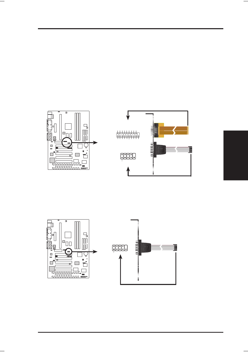
20) Digital LCD Header (20-1 pin DFP) available on LCD model only
This header requires a digital LCD cable connector. For the LCD model, the
individual serial cable with bracket is replaced with the LCD and serial combi-
nation cable with bracket (as shown here). Connect the digital LCD cable to the
LCD header and the serial cable to the COM2 header and mount the bracket to
the chassis on a free expansion slot. NOTE: If both CRT and digital LCD moni-
tors are used, the CRT will take precedent. This connector is for a digital LCD
panel; an analog LCD panel comes with a 15-pin VGA cable connector to be
used on the monitor connector. The connectors with bracket shown here are
provided with the LCD model.
P3W-E LCD and COM2 Bracket
DFP
to LCD Header
to COM2 Header
Pin 1
COM2
1
5VL
TVCL
HPG
GND
TXC+
TX0-
TX1+
TX2-
GND
(NC)
5VL
TVD
A
0+5V
TXC-
GND
TX0+
TX1-
GND
TX2+
11
10
20
GND
(NC)
1
01
01
®
P3W-E
21) Serial Port COM 2 Header (10-1 pin COM2)
The optional serial port bracket can be used to add an additional serial port for
additional serial devices. The connector with bracket shown here is for the non-
LCD model.
P3W-E Serial COM2 Bracket
Pin 1
to COM2 Header
1
01
01
®
P3W-E