Hardware setup, 1 motherboard layout, 14 asus p3w-e user’s manual – Asus P3W-E User Manual
Page 14: Intel 810e, Pci1 pci2 pci4 pci3, Pci5, Pci6, Slot1, Isa1 isa2, Multi-i/o
14
ASUS P3W-E User’s Manual
3. HARDWARE SETUP
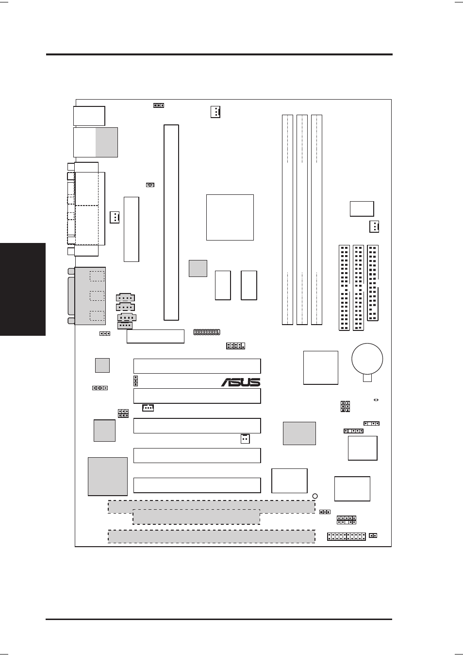
Motherboard Layout
3. H/W SETUP
NOTES: Grayed items are optional at the time of purchase.
The PCI/ISA configuration is dependent on territory.
3.1 Motherboard Layout
COM1
P
ARALLEL
PORT
VGA
PS/2
T: Mouse
B: Keyboard
CPU_FAN
Intel 810e
Graphics &
Memory
Controller
Hub (GMCH)
01
DIMM1 (64/72 bit, 168-pin module)
0 1
PWR_F
AN
WOR
WOL_CON
CHASIS
(ACHA)
VIDEO
MODEM
GAME_AUDIO
Mic
In
Line
Out
Line
In
CHA_FAN
CD1
AUX
SMB
PCI1
PCI2
PCI4
PCI3
PANEL
IDELED
FLOPPY
SECOND
AR
Y
IDE
PRIMAR
Y
IDE
ISA1
ISA2
A
TX Power Connector
IR
CLRTC
Intel I/O
Controller
Hub (ICH)
01
DIMM2 (64/72 bit, 168-pin module)
2 3
01
DIMM3 (64/72 bit, 168-pin module)
3 2
CR2032 3V
Lithium Cell
CMOS Power
Row
DIP
Switches
PCI5
INT
MIC
COM2
LAN_EN
PCI3VSEL
SPEAKER
(SPKR)
Audio Modem Riser
(AMR)
Bottom:
USB1
USB2
Multi-I/O
®
P3W-E
4Mbit
Firmware
Hub
ASUS
ASIC
with Hardware
Monitor
PLED2
Audio
Codec
Intel Fast
Ethernet
SPK
2MB
SDRAM
2MB
SDRAM
LCD Header
(DFP)
PCI to ISA
Bridge
LCD
Encoder
PCI6
JEN
VIO
Top:
RJ45
SAFE_MD
NO_REBOOT
32-bit PCI
Audio
Chipset
Slot1
JTPWR