Hardware setup – Asus P3W-E User Manual
Page 37
ASUS P3W-E User’s Manual
37
3. HARDWARE SETUP
Connectors
3. H/W SETUP
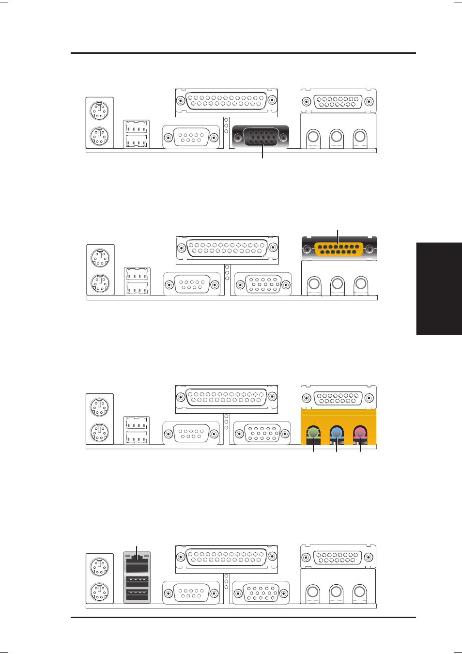
6) Monitor Output Connector (Blue 15-pin VGA)
This connector is for output to a VGA-compatible device.
7) Joystick/MIDI Connector (Gold 15-pin GAME_AUDIO) (optional)
You may connect game joysticks or game pads to this connector for playing
games. Connect MIDI devices for playing or editing professional audio.
Joystick/MIDI (15-pin female)
8) Audio Port Connectors (Three 1/8” GAME_AUDIO) (optional)
Line Out (lime) can be connected to headphones or preferably powered speak-
ers. Line In (light blue) allows tape players or other audio sources to be re-
corded by your computer or played through the Line Out (lime). Mic (pink)
allows microphones to be connected for inputting voice.
Mic
Line In
Line Out
1/8" Stereo Audio Connectors
9) Fast-Ethernet Port Connector (RJ45) (optional)
The RJ45 connector is optional at the time of purchase and is located on top of
the USB connectors. The connector allows the motherboard to connect to a Lo-
cal Area Network (LAN) through a network hub.
RJ45