Asus P5ND2-SLI Deluxe User Manual
Page 52
2 - 2 6
2 - 2 6
2 - 2 6
2 - 2 6
2 - 2 6
C h a p t e r 2 : H a r d w a r e i n f o r m a t i o n
C h a p t e r 2 : H a r d w a r e i n f o r m a t i o n
C h a p t e r 2 : H a r d w a r e i n f o r m a t i o n
C h a p t e r 2 : H a r d w a r e i n f o r m a t i o n
C h a p t e r 2 : H a r d w a r e i n f o r m a t i o n
2 .
2 .
2 .
2 .
2 .
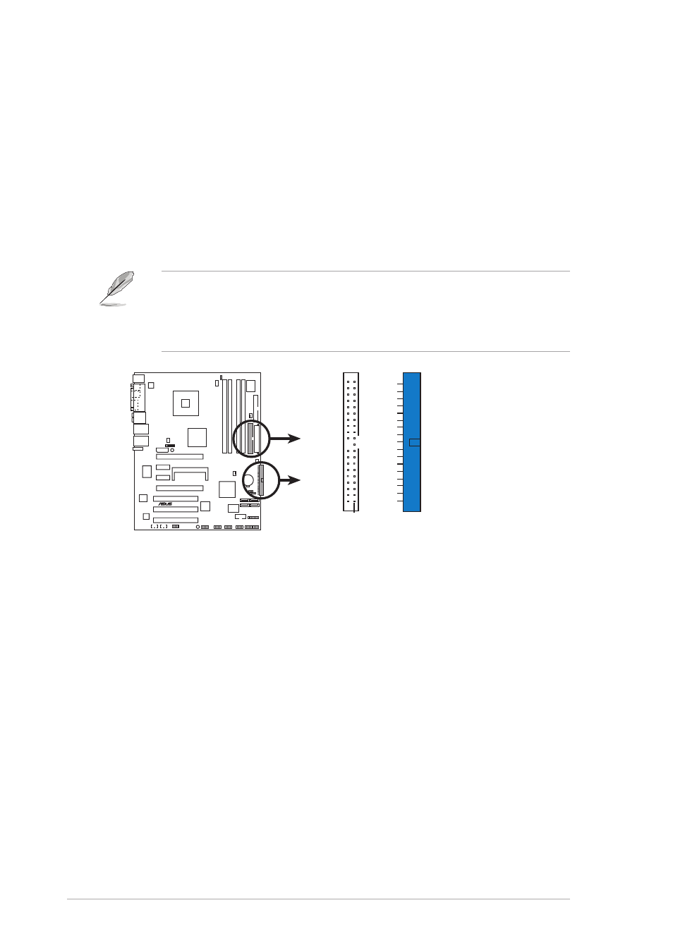
I D E c o n n e c t o r s ( 4 0 - 1 p i n P R I _ I D E , S E C _ I D E )
I D E c o n n e c t o r s ( 4 0 - 1 p i n P R I _ I D E , S E C _ I D E )
I D E c o n n e c t o r s ( 4 0 - 1 p i n P R I _ I D E , S E C _ I D E )
I D E c o n n e c t o r s ( 4 0 - 1 p i n P R I _ I D E , S E C _ I D E )
I D E c o n n e c t o r s ( 4 0 - 1 p i n P R I _ I D E , S E C _ I D E )
These connectors are for Ultra DMA 133/100/66 signal cables. The
Ultra DMA 133/100/66 signal cable has three connectors: a blue
connector for the primary IDE connector on the motherboard, a black
connector for an Ultra DMA 133/100/66 IDE slave device (optical
drive/hard disk drive), and a gray connector for an Ultra DMA 133/
100/66 IDE master device (hard disk drive). If you install two hard disk
drives, you must configure the second drive as a slave device by setting
its jumper accordingly. Refer to the hard disk documentation for the
jumper settings.
•
Pin 20 on the IDE connector is removed to match the covered hole
on the Ultra DMA cable connector. This prevents incorrect insertion
when you connect the IDE cable.
•
Use the 80-conductor IDE cable for Ultra DMA 100/66 IDE devices.
P5ND2-SLI
®
P5ND2-SLI DELUXE IDE connectors
NOTE: Orient the red markings
(usually zigzag) on the IDE
ribbon cable to PIN 1.
PRI_IDE
PIN 1
SEC_IDE