4 layout contents, 3 central processing unit (cpu), 1 installing the cpu – Asus M4A78LT PLUS User Manual
Page 14: Layout contents -4, Central processing unit (cpu) -4 1.3.1, Installing the cpu -4
1.2.4
Layout contents
Connectors/Jumpers/Slots/LED
Page Connectors/Jumpers/Slots/LED
Page
1. USB device wake-up (3-pin USBPW1-6, USBPW7-10) 1-15 8. System panel connector (10-1 pin PANEL)
1-20
2. Keyboard power (3-pin KBPWR)
1-15 9. Speaker connector (4-pin SPEAKER)
1-19
3. CPU and chassis fan connectors (4-pin CPU_FAN,
3-pin CHA_FAN)
1-17 10. USB 2.0 connectors (10-1 pin USB78,
USB910)
1-21
4. ATX power connectors (24-pin EATXPWR, 4-pin
ATX12V)
1-18 11. Chassis intrusion connector (4-1 pin
CHASSIS)
1-21
5. AM3 CPU socket
1-4 12. Clear RTC RAM (3-pin CLRTC)
1-14
6. DDR3 DIMM slots
1-7 13. Front panel audio connector (10-1 pin AAFP) 1-17
7. SATA 3.0Gb/s connectors (7-pin SATA6G_1~4)
1-19
1.3
Central Processing Unit (CPU)
This motherboard comes with an AM3 socket designed for Phenom™ II / Athlon™ II /
Sempron™ 100 series processors.
1.3.1
Installing the CPU
To install a CPU:
1.
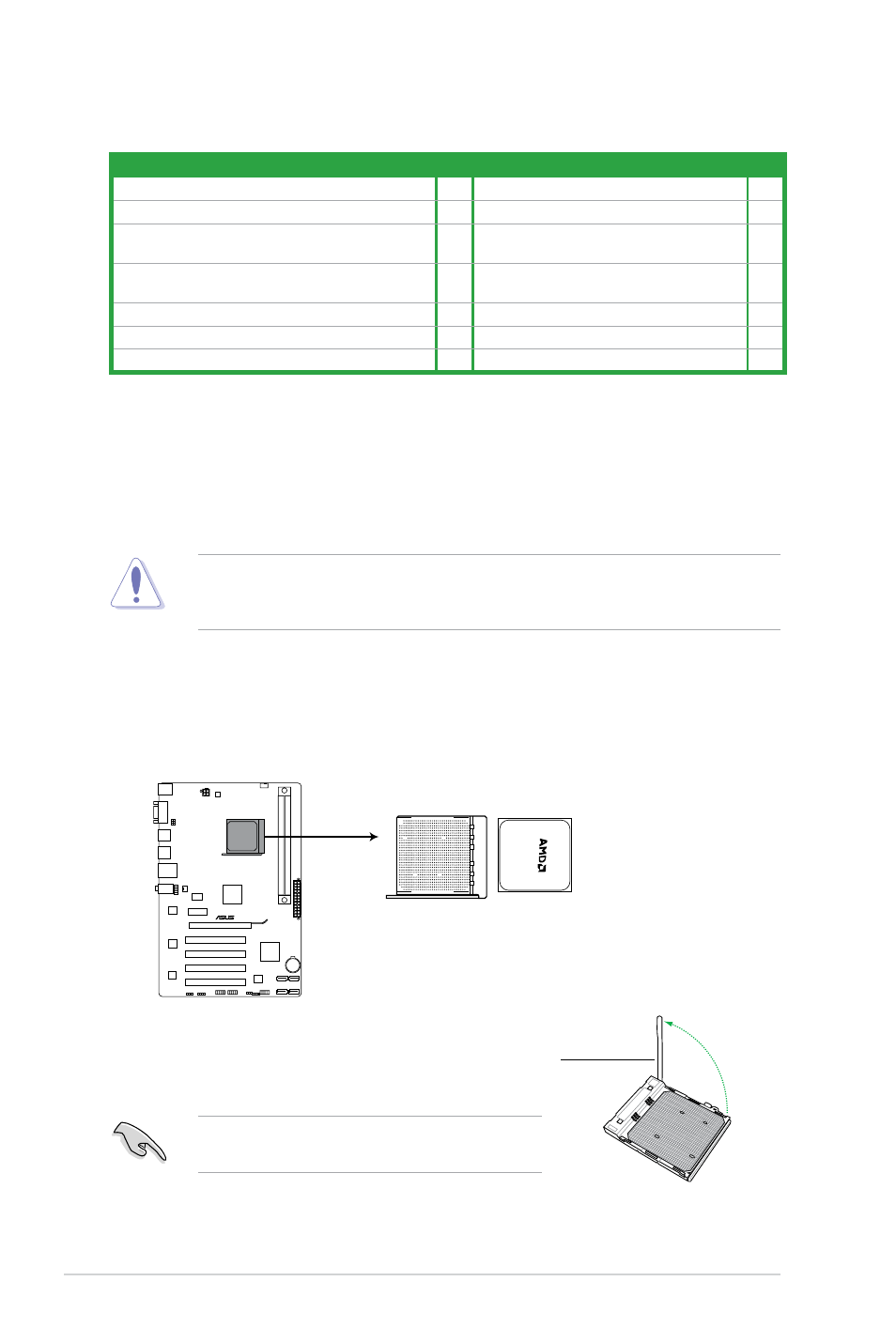
Locate the CPU socket on the motherboard.
The AM3 socket has a different pinout from the AM2+/AM2 socket. Ensure that you use a
CPU designed for the AM3 socket. The CPU fits in only one correct orientation. DO NOT
force the CPU into the socket to prevent bending the pins and damaging the CPU!
M4A78LT PLUS
M4A78LT PLUS CPU socket AM3
2.
Press the lever sideways to unlock the
socket, then lift it up to a 90°-100° angle.
Socket lever
Ensure that the socket lever is lifted up to a 90°-100°
angle; otherwise, the CPU will not fit in completely.
Chapter 1: Product introduction
1-4