Asus Blitz Formula (Special Edition) User Manual
Page 28
2-2
Chapter 2: Hardware information
2. Memory LED
Refer to the illustration below for the location of the memory LED and the
table below for LED definition.
BLITZ FORMULA
®
BLITZ FORMULA DDR LED
DDR_CRAZY
DDR_HIGH
DDR_NORMAL
BLITZ FORMULA
®
BLITZ FORMULA North/South Bridge LED
NB_CRAZY
NB_HIGH
NB_NORMAL
SB_CRAZY
SB_HIGH
SB_NORMAL
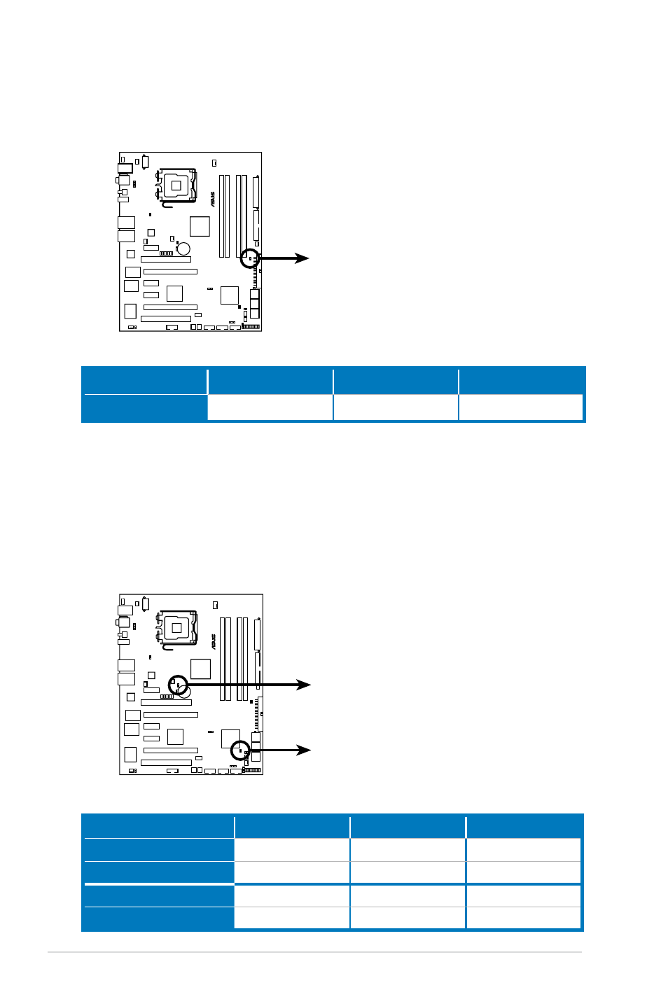
3. Northbridge/Southbridge LEDs
The northbridge and southbridge LEDs each have two different voltage
displays. The northbridge LED displays either the North Bridge Voltage or the
FSB Termination Voltage. The southbridge LED shows either the PLL Voltage
or the South Bridge Voltage. You can select the voltage to display in BIOS.
Refer to the illustration below for the location of the northbridge/southbridge
LEDs and the table below for LED definition.
Normal (green)
High (yellow)
Crazy (red)
DRAM Voltage
1.80~2.20
2.22~2.60
2.62~3.40
Normal (green)
High (yellow)
Crazy (red)
North Bridge Voltage
1.25~1.59
1.61~1.83
1.85~2.03
FSB Termination Voltage
1.20~1.40
1.42~1.60
1.62~1.80
PLL Voltage
1.50~1.60
1.62~1.80
1.82~2.00
SB Bridge Voltage
1.050~1.125
1.150~1.175
1.200~1.225