1 introduction, 2 motherboard layout, Pci1 – Asus Terminator C3 User Manual
Page 52
4 - 2
4 - 2
4 - 2
4 - 2
4 - 2
C h a p t e r 4 : M o t h e r b o a r d i n f o r m a t i o n
C h a p t e r 4 : M o t h e r b o a r d i n f o r m a t i o n
C h a p t e r 4 : M o t h e r b o a r d i n f o r m a t i o n
C h a p t e r 4 : M o t h e r b o a r d i n f o r m a t i o n
C h a p t e r 4 : M o t h e r b o a r d i n f o r m a t i o n
4.1
Introduction
The ASUS C3V motherboard comes already installed in the ASUS
Terminator 1 C3 barebone system. This chapter provides technical
information about the motherboard for future upgrades or system
reconfiguraiton.
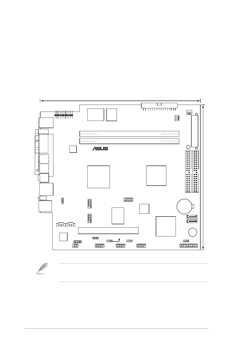
4.2
Motherboard layout
23cm (9.06in)
CHA_FAN
FLOPPY
CD
AD1888
AUX
PANEL
USB34
USBPWR12
C3V
MIC_LOUT
®
IOC_MB1
DDR DIMM2 (64/72-bit, 184-pin module)
PCI1
VIA
VT6307
Flash
BIOS
22.4cm (8.82in)
PS/2
T:Mouse
B:Keyboard
RJ-45
USB_12
T:Port0
B:Port1
DDR DIMM1 (64/72-bit, 184-pin module)
SEC_IDE
ATX12V
SPDIF_OUT
LANLED
P
ARALLEL
PORT
VGA
Mic
In
Line
In
Line
Out
BUZZ1
CLRTC
PRI_IDE
CPU_FAN
SATA2
SB_PWR
A
TXPWR
VIA
VT8237 CD
SATA1
CR2032 3V
Lithium Cell
CMOS Power
VIA
CLE266
USB78
USB56
USBPWR34
USBPWR56
USBPWR78
Super
I/O
VIA C3
CPU
IE1394_1
IE1394_2
VIA
VT1622A
J1
•
The IE1394_1 and IE1394_2 connectors are optional.
•
The J1 connector is for the optional TV-out and S-Video out ports.