4 detaching the drive frame – Asus Terminator C3 User Manual
Page 20
2 - 4
2 - 4
2 - 4
2 - 4
2 - 4
C h a p t e r 2 : B a s i c I n s t a l l a t i o n
C h a p t e r 2 : B a s i c I n s t a l l a t i o n
C h a p t e r 2 : B a s i c I n s t a l l a t i o n
C h a p t e r 2 : B a s i c I n s t a l l a t i o n
C h a p t e r 2 : B a s i c I n s t a l l a t i o n
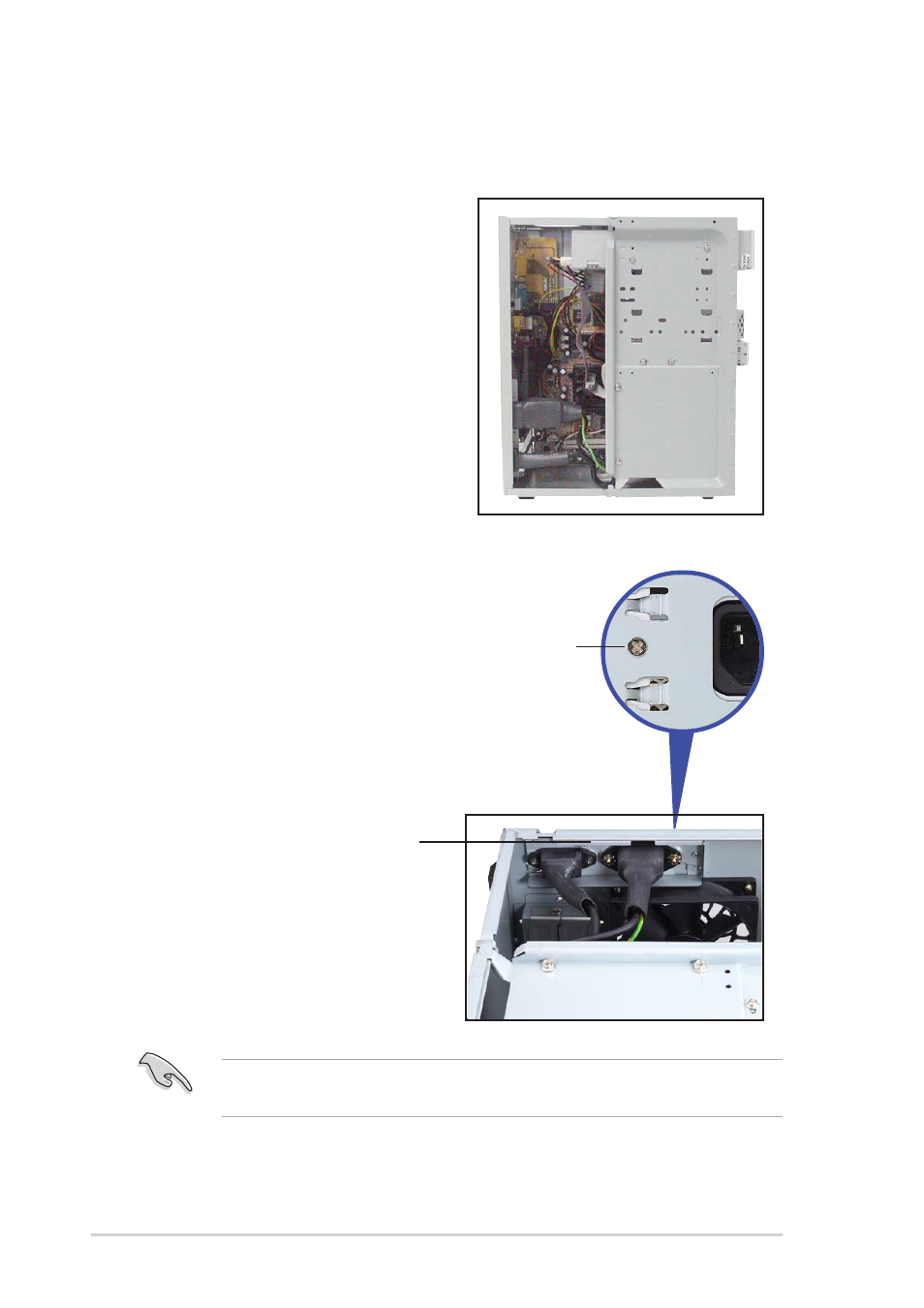
2.4
Detaching the drive frame
You must release the power socket module from the rear panel before
detaching the drive frame to avoid breaking the power cable.
Follow these steps to detach the
drive frame.
1.
Place the chassis on a flat
surface and turn it on its side.
2.
The power socket and voltage
selector switch are attached to
a metal module secured to the
rear panel by a screw. Remove
the screw to release the power
socket module.
Power socket
module screw
P o w e r s o c k e t m o d u l e
P o w e r s o c k e t m o d u l e
P o w e r s o c k e t m o d u l e
P o w e r s o c k e t m o d u l e
P o w e r s o c k e t m o d u l e
- CG8565 (410 pages)
- CG8565 (246 pages)
- CS5111 (26 pages)
- CS5120 (1 page)
- ET1611PUK (38 pages)
- S2-P8H61E (80 pages)
- P2-PH1 (80 pages)
- P1-P5945G (80 pages)
- P2-P5945GCX (90 pages)
- CG8270 (536 pages)
- CG8270 (72 pages)
- CG8270 (76 pages)
- CG8270 (534 pages)
- CG8270 (362 pages)
- CG8270 (218 pages)
- P3-P5G31 (100 pages)
- P3-PH4 (80 pages)
- P2-M2A690G (80 pages)
- P2-M2A690G (8 pages)
- P4-P5N9300 (82 pages)
- P4-P5N9300 (1 page)
- P1-P5945GC (92 pages)
- P2-P5945GC (92 pages)
- P3-P5G33 (98 pages)
- T3-P5945GC (80 pages)
- T3-P5945GCX (80 pages)
- P2-M2A690G (94 pages)
- T3-PH1 (80 pages)
- T3-PH1 (82 pages)
- T5-P5G41E (76 pages)
- T5-P5G41E (82 pages)
- S1-AT5NM10E (68 pages)
- P6-P7H55E (67 pages)
- ES5000 (174 pages)
- T4-P5G43 (104 pages)
- T-P5G31 (92 pages)
- BT6130 (54 pages)
- BT6130 (2 pages)
- BT6130 (60 pages)
- CG8265 (350 pages)
- CG8265 (210 pages)
- CM1740 (70 pages)
- CM1740 (198 pages)
- CM1740 (330 pages)
- P6-M4A3000E (59 pages)