Asus P4RD1-MX User Manual
Page 38
1-26
Chapter 1: Product introduction
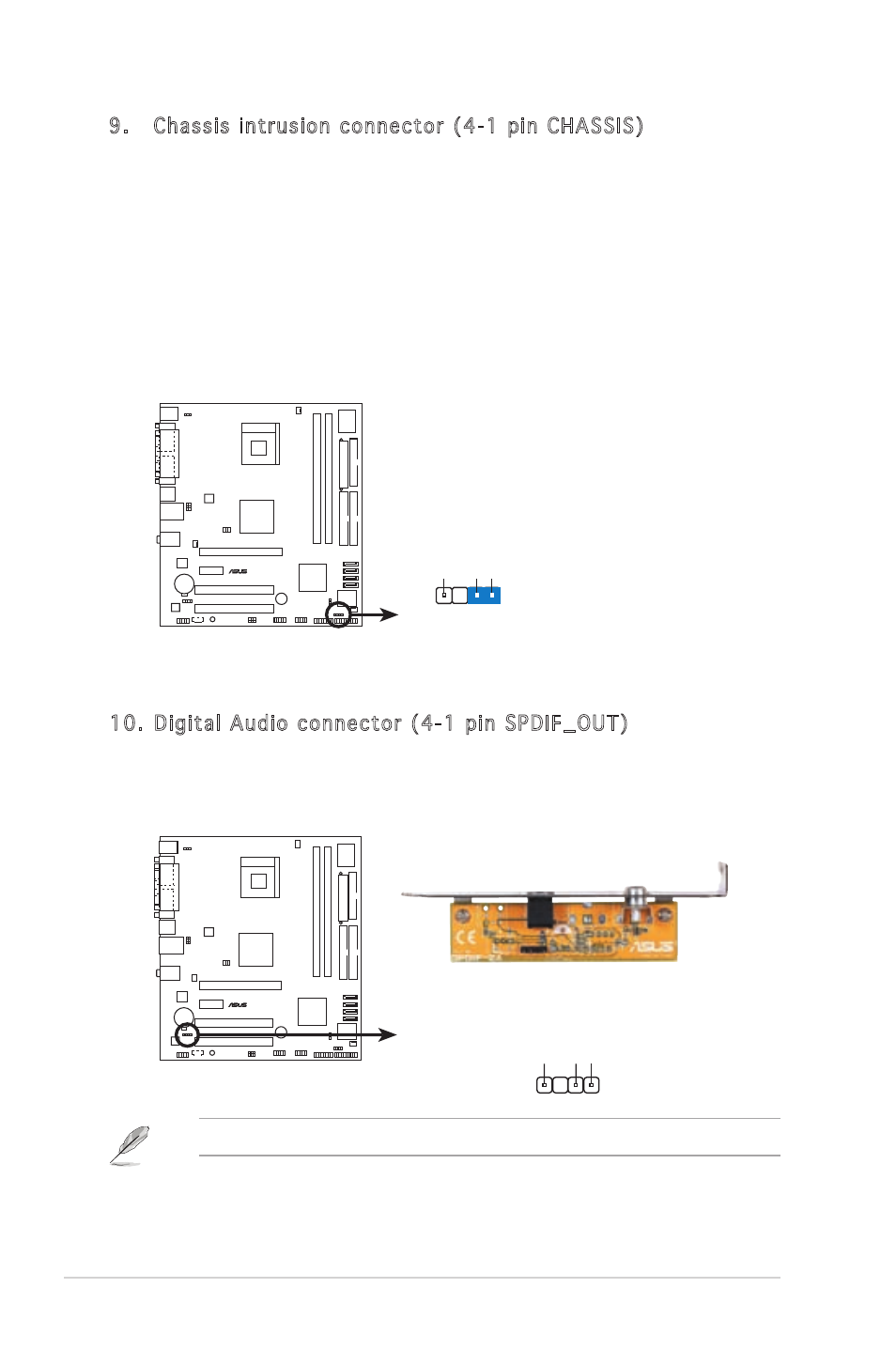
10. Digital Audio connector (4-1 pin SPDIF_OUT)
This connector is for the S/PDIF audio module to allow digital sound
output. Connect one end of the S/PDIF audio cable to this connector
and the other end to the S/PDIF module.
The S/PDIF module is purchased separately.
P4RD1-MX
®
P4RD1-MX Digital audio connector
+5V
SPDIFOUT GND
SPDIF_OUT
9. Chassis intrusion connector (4-1 pin CHASSIS)
This connector is for a chassis-mounted intrusion detection sensor
or switch. Connect one end of the chassis intrusion sensor or switch
cable to this connector. The chassis intrusion sensor or switch sends
a high-level signal to this connector when a chassis component
is removed or replaced. The signal is then generated as a chassis
intrusion event.
By default, the pins labeled “Chassis Signal” and “Ground” are shorted
with a jumper cap. Remove the jumper caps only when you intend to
use the chassis intrusion detection feature.
P4RD1-MX
®
P4RD1-MX Chassis intrusion connector
CHASSIS
+5VSB_MB
Chassis Signal GND
(Default)