2 internal connectors, 2 internal connectors -23, P5p41c analog front panel connector – Asus P5P41C User Manual
Page 33
ASUS P5P41C
1-23
7.
USB 2.0 ports 1 and 2. These two 4-pin Universal Serial Bus (USB) ports are
available for connecting USB 2.0 devices.
8.
USB 2.0 ports 3 and 4. These two 4-pin Universal Serial Bus (USB) ports are
available for connecting USB 2.0 devices.
9.
COM port. This port is for pointing devices or other serial devices.
10. PS/2 Keyboard port (purple). This port is for a PS/2 keyboard.
1.10.2
Internal connectors
1.
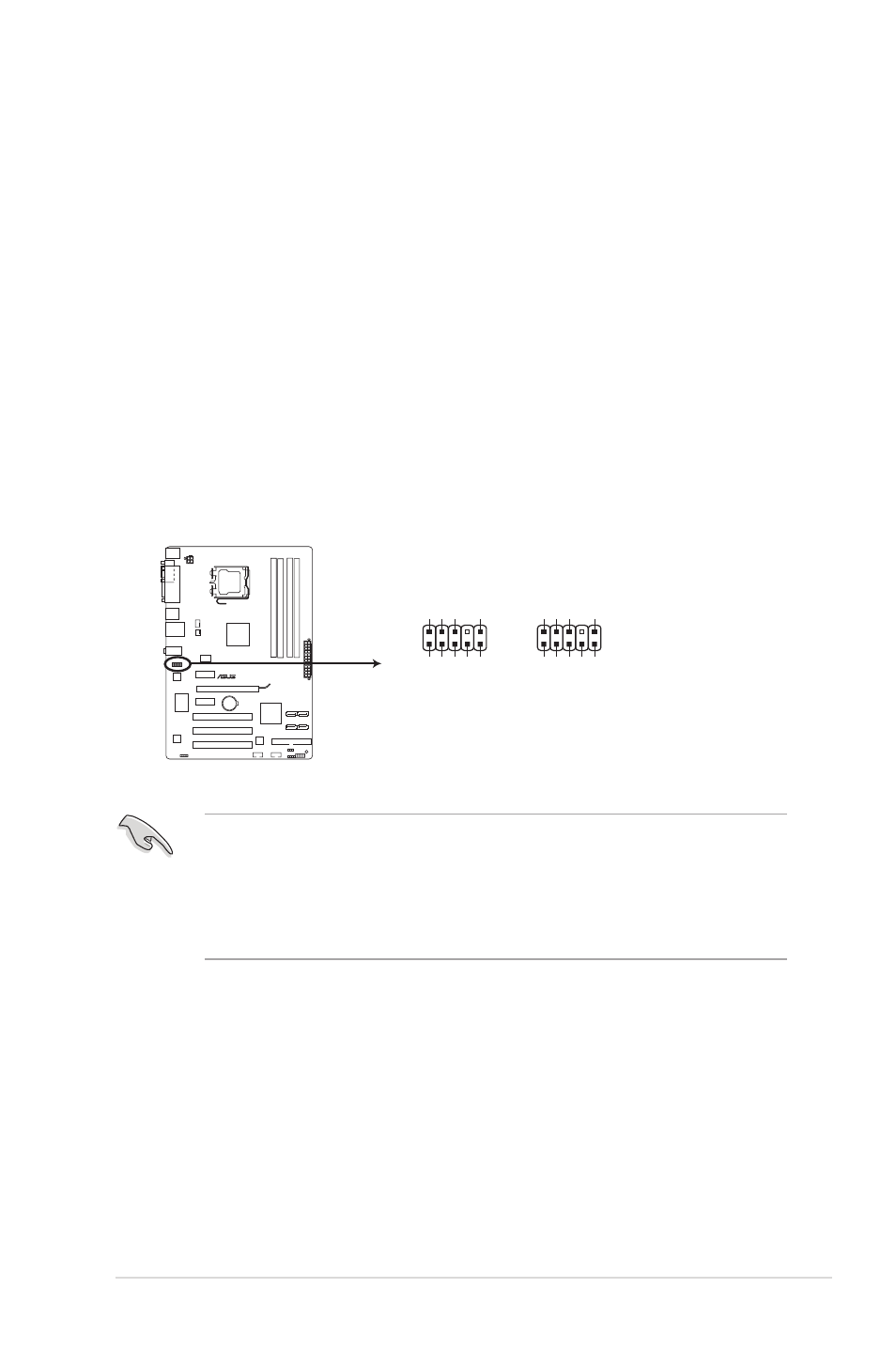
Front panel audio connector (10-1 pin AAFP)
This connector is for a chassis-mounted front panel audio I/O module that supports
either HD Audio or legacy AC`97 audio standard. Connect one end of the front panel
audio I/O module cable to this connector.
• We recommend that you connect a high-definition front panel audio module to this
connector to avail of the motherboard’s high-definition audio capability.
• If you want to connect a high-definition front panel audio module to this connector, set
the Front Panel Type item in the BIOS setup to [HD Audio]. If you want to connect an
AC'97 front panel audio module to this connector, set the item to [AC97]. By default, this
connector is set to [HD Audio]. See section 2.4.3 Chipset for details.
P5P41C
P5P41C Analog front panel connector
AAFP
PIN 1
GN
D
PRESENCE#
SENSE1_RETUR
SENSE2_RETUR
PORT1
L
PORT1
R
PORT2
R
SENSE_SEND
PORT2
L
HD-audio-compliant
pin definition
PIN 1
AGND
NC
NC
NC
MIC
2
MICPWR
Line out_
R
NC
Line out_L
Legacy AC’97
compliant definition