Hardware setup, Asus a7s-vm user’s manual 37 – Asus A7S-VM User Manual
Page 37
ASUS A7S-VM User’s Manual
37
3. HARDWARE SETUP
Connectors
3. H/W SETUP
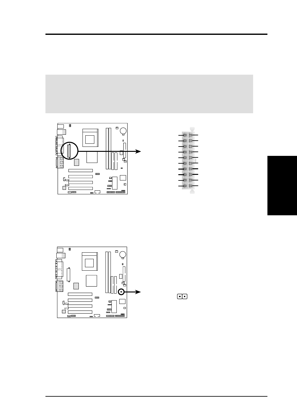
17) ATX Power Supply Connector (20-pin block ATXPWR)
This connector connects to an ATX power supply. The plug from the power supply
fits in only one orientation because of the different hole sizes. Find the proper
orientation and push down firmly making sure that the pins are aligned.
IMPORTANT:
Make sure that the ATX power supply can supply at least 10mA
on the +5-volt standby lead (+5VSB). You may experience difficulty in turning
the system ON if the power supply cannot support the load. For Wake-On-LAN
support, the ATX power supply must supply at least 720mA +5VSB.
A7S-VM Thermal Sensor Connector
PWR_TMP
Power Supply Thermal Sensor
A7S-VM
18) Power Supply Thermal Sensor Connector (2-pin PWR_TMP)
If you have a power supply with thermal monitoring capability, connector its
thermal sensor cable to this connector.
A7S-VM
A7S-VM ATX Power Connector
+3.3 Volts
-12.0 Volts
Ground
Power Supply On
Ground
Ground
Ground
NC
+5.0 Volts
+5.0 Volts
Power Good
+12.0 Volts
+3.3 Volts
+3.3 Volts
Ground
+5.0 Volts
Ground
+5.0 Volts
Ground
+5V Standby