Hardware setup, Asus a7s-vm user’s manual 33 – Asus A7S-VM User Manual
Page 33
ASUS A7S-VM User’s Manual
33
3. HARDWARE SETUP
Connectors
3. H/W SETUP
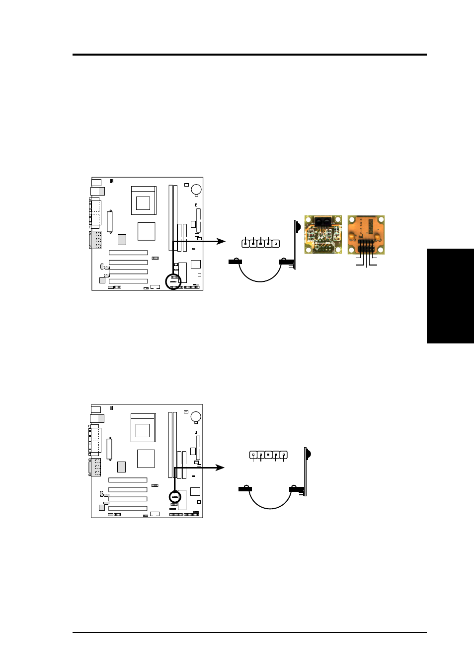
9) Standard Infrared Module Connector (5-pin IR)
This connector supports an optional wireless transmitting and receiving infrared
module. This module mounts to a small opening on a system chassis that supports
this feature. You must also configure the setting through UART2 Use Infrared
(see 4.4.2 I/O Device Configuration) to select whether UART2 is directed for
use with COM2 or IrDA. Use the five pins as shown in Back View and connect
a ribbon cable from the module to the motherboard SIR connector according to
the pin definitions.
A7S-VM
A7S-VM Infrared Module Connector
Front View
Back View
+5V
IRTX
IRRX
(NC)
GND
+5V
IRRX
IR
TX
(NC)
GND
IR
1
A7S-VM
A7S-VM Infrared Module Connector
(NC)
GND
CIRRX
CIR+5V
CIR
10) Consumer Infrared Module Connector (5-pin CIR)
This connector supports the optional Consumer Infrared (CIR) set to allow
wireless transmitting and remote functions through one external infrared module.
Enable the Wake On PS2 KB/Mouse item in section 4.5.1 Power Up Control if
you wish to use the CIR power up feature.