Hardware setup, Asus a7s-vm user’s manual 35 – Asus A7S-VM User Manual
Page 35
ASUS A7S-VM User’s Manual
35
3. HARDWARE SETUP
Connectors
3. H/W SETUP
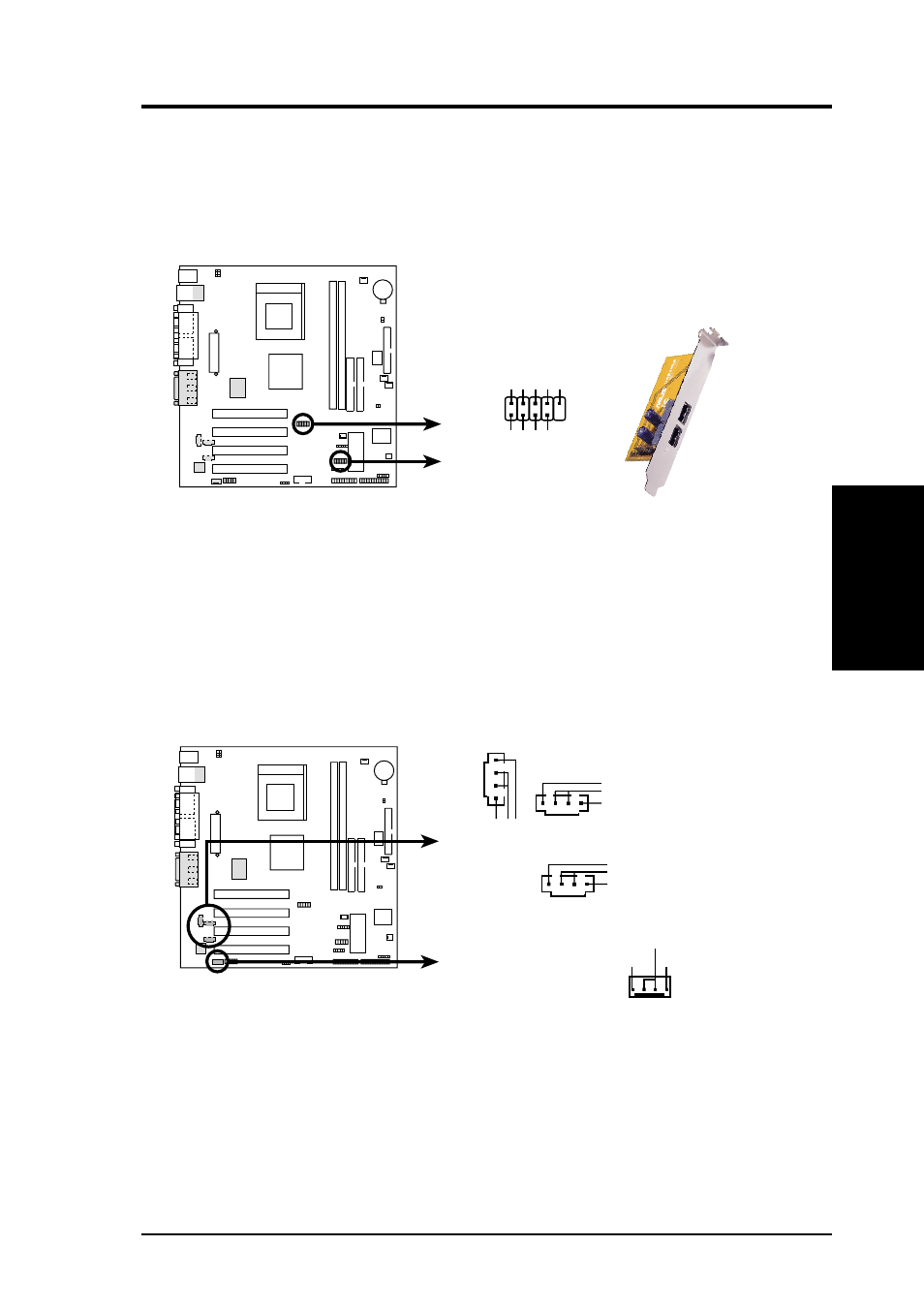
14) Internal Audio and Video Connectors (4-1 pin CD, VIDEO, AUX, MODEM)
These connectors allow you to receive stereo audio input from sound sources
such as a CD-ROM, TV tuner, or MPEG card. The MODEM connector allows
the onboard audio to interface with a voice modem card with a similar connector.
It also allows the sharing of mono_in (such as a phone) and a mono_out (such as
a speaker) between the audio and the voice modem card.
13) USB Headers (10-1 pin USBP1, USBP2)
If the USB ports on the back panel are inadequate, two USB headers are available
for four additional USB ports. Connect a 2-port USB connector set to one USB
header then mount the bracket to an open slot on the chassis. (NOTE: The USB
connector set does not come with the motherboard package.)
A7S-VM
A7S-VM USB Port
USB Power
USBP2
–
USBP2+
GND
NC
USB Power
USBP3
–
USBP3+
GND
1
5
6
10
USBP2
USBP1
Modem-Out
(from Modem)
Ground
Modem-In
(to Modem)
CD (Black)
Right A
udio Channel
Left A
udio Channel
Ground
A7S-VM
A7S-VM Internal Audio Connectors
AUX (White)
Right Audio Channel
Left Audio Channel
Ground
VIDEO (Green)
Right Audio Channel
Left Audio Channel
Ground
MODEM