3 install a cpu – Asus Terminator P-III User Manual
Page 17
ASUS Terminator Barebone System
17
2.3 Install a CPU
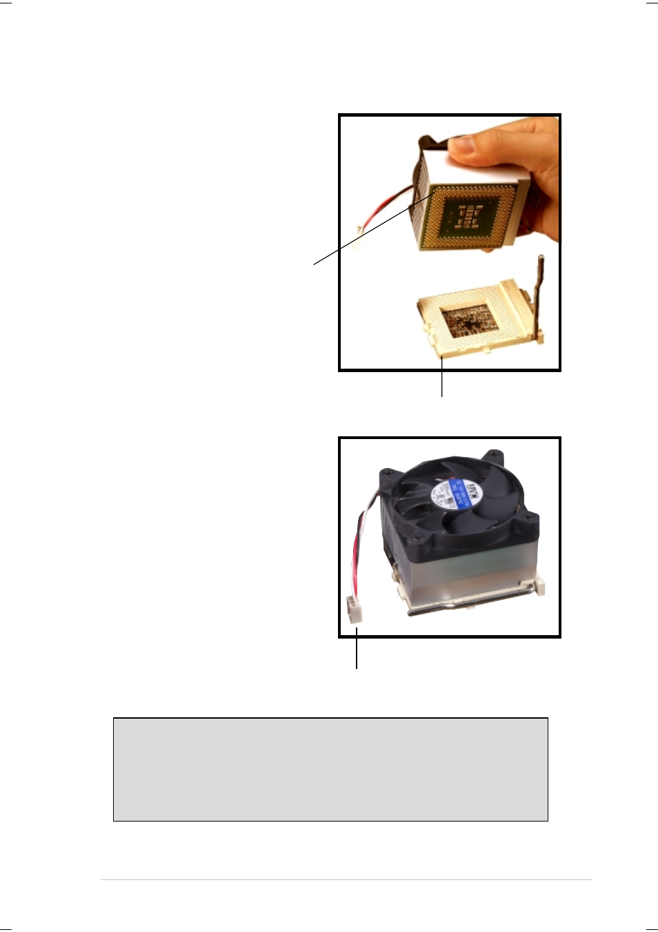
3. Position the CPU above the
socket such that its notched
or marked corner matches the
Socket Pin 1, while making
sure that the CPU is parallel
to the socket.
4. Carefully insert the CPU into
the socket until it fits in place.
WARNING!
The CPU fits only in one orientation. DO NOT force the CPU into
the socket to prevent bending the pins and damaging the CPU. If
the CPU does not fit completely, check its orientation or check for
bent pins.
Socket Pin 1
Notched Corner
5. Push down the lever to secure
the CPU. The lever clicks in
place indicating that the
socket is locked.
6. Connect the CPU fan cable to
the 3-pin CPU_FAN connector
on the motherboard. Refer to
the picture in step 1.
CPU Fan Cable
See also other documents in the category Asus Computers:
- CG8565 (410 pages)
- CG8565 (246 pages)
- CS5111 (26 pages)
- CS5120 (1 page)
- ET1611PUK (38 pages)
- S2-P8H61E (80 pages)
- P2-PH1 (80 pages)
- P1-P5945G (80 pages)
- P2-P5945GCX (90 pages)
- CG8270 (218 pages)
- CG8270 (536 pages)
- CG8270 (72 pages)
- CG8270 (76 pages)
- CG8270 (534 pages)
- CG8270 (362 pages)
- P3-PH4 (80 pages)
- P3-P5G31 (100 pages)
- P2-M2A690G (80 pages)
- P2-M2A690G (8 pages)
- P4-P5N9300 (1 page)
- P4-P5N9300 (82 pages)
- P1-P5945GC (92 pages)
- P2-P5945GC (92 pages)
- P3-P5G33 (98 pages)
- T3-P5945GC (80 pages)
- T3-P5945GCX (80 pages)
- P2-M2A690G (94 pages)
- T3-PH1 (80 pages)
- T3-PH1 (82 pages)
- T5-P5G41E (82 pages)
- T5-P5G41E (76 pages)
- S1-AT5NM10E (68 pages)
- P6-P7H55E (67 pages)
- ES5000 (174 pages)
- T4-P5G43 (104 pages)
- T-P5G31 (92 pages)
- BT6130 (60 pages)
- BT6130 (54 pages)
- BT6130 (2 pages)
- CG8265 (350 pages)
- CG8265 (210 pages)
- CM1740 (330 pages)
- CM1740 (70 pages)
- CM1740 (198 pages)
- P6-M4A3000E (59 pages)