Gigabit fiber port aggregator tap – Net Optics GigaBit Fiber SFP Port Aggregator Tap User Manual
Page 9
GigaBit Fiber Port Aggregator Tap
5
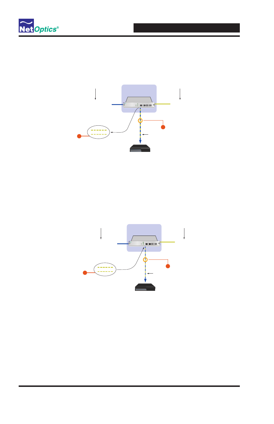
Figure 2: Aggregated traffic is greater than NIC's capacity
Figure 3: Traffic burst has passed
Using a single NIC, the monitoring
device receives 1000 Mbps of combined
traffic from Side A and Side B, including
physical layer errors.
The extra 400 Mbps of traffic is
stored in the 512 megabyte buffer
for Port A. Memory continues to
fill until the 512 megabyte capacity
is reached, or the burst ends.
(A separate 512 megabyte buffer is
also available to handle a burst
on Port B.)
GigaBit SX SFP
Port Aggregator Tap
Span Port 2
Span Port 1
Monitoring Device
1
Side A
Side B
Side A +
Side B
2
Memory
State 2: Side A + Side B becomes greater than 100%
of the NIC's receive capacity.
Example: There is a burst of traffic, so Side A is now at 900 Mbps while
Side B remains at 500 Mbps. The NIC's utilization is at 140%, requiring
the use of memory to help prevent data loss.
1
2
Network
OUT
IN
OUT
IN
A
B
Port Aggregator
1
Network
Monitor
2
A
B
Once the memory has cleared, the
monitoring device begins receiving
new data directly from the link. Using
a single NIC, the monitoring device
receives all traffic from Side A and
Side B, including physical layer errors.
The Tap applies a first-in, first-out
process to all packets. Once the burst
has ended and the NIC's utilization is
again below 100 percent, the Tap first
processes the packets that were stored
in memory. As long as the NICʼs
utilization remains below 100 percent,
this process continues uninterrupted
until the memory clears.
GigaBit SX SFP
Port Aggregator Tap
Span Port 2
Sapn Port 1
Monitoring Device
2
Side A
Side B
Side A +
Side B
1
Memory
State 3: Side A + Side B is once again less than 100%
of the NIC's receive capacity.
Example: On a 1000 Mbps link, Side A is again at 300 Mbps and Side B
remains at 500 Mbps. The NIC's utilization is again at 80%.
1
2
Network
OUT
IN
OUT
IN
A
B
Port Aggregator
1
Network
Monitor
2
A
B