About this guide, Product diagram, Led indicators – Net Optics GigaBit Fiber SFP Port Aggregator Tap User Manual
Page 7: Gigabit fiber port aggregator tap
GigaBit Fiber Port Aggregator Tap
3
About this Guide
This Guide provides you all the information you need to install and operate
the GigaBit Fiber Port Aggregator Tap . Please read the entire Guide before
attempting to install or operate the Tap .
This Guide covers the following models:
Part Number
Description
TPA-SX4-SFP
GigaBit Port Aggregator, multimode SX fiber, 60/40 split
ratio, two SPF monitor ports
TPA-SX5-SFP
GigaBit Port Aggregator, multimode SX fiber, 50/50 split
ratio, two SPF monitor ports
TPA-LX4-SFP
GigaBit Port Aggregator, singlemode LX fiber, 60/40 split
ratio, two SPF monitor ports
TPA-LX5-SFP
GigaBit Port Aggregator, singlemode SX fiber, 50/50 split
ratio, two SPF monitor ports
TPA-50SX5-SFP
GigaBit Port Aggregator, multimode 50um SX fiber,
50/50 split ratio, two SPF monitor ports
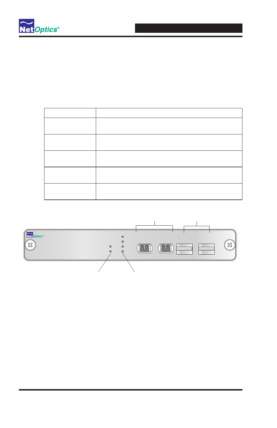
Product Diagram
Figure 4: Front Panel
LED Indicators
• PWR 1/ PWR 2: Main and Redundant Power . If the Tap is deployed with
both power supplies, both LEDs illuminate when the Tap is plugged in . If
an LED is off, this indicates that the corresponding power supply is not
functioning .
• Link/Activity Indicators: If a good link is established, the LED illu-
minates a steady green . If there is current activity on this link, the LED
flashes.
Power LEDs
www.netoptics.com
Port Aggregator
1
Network
Monitor
2
A
B
1
2
2
1
B
A
LINK
Monitor Ports
with plugs
Network Ports
Link LEDs