Q-Tech QT24T User Manual
Page 2
MIL-PRF-55310/21G
2
NOTES:
1.
Dimensions are in inches.
2.
Metric equivalents are given for general information only.
3.
Unless otherwise specified, tolerances are ±.005 (0.13 mm) for three place decimals and ±.02 (0.5 mm) for
two place decimals.
4.
The leads shall be symmetrical with respect to the package so that the spacing between the first lead and the
end of the package shall be equidistant on each side.
5.
Unit shall meet all requirements with pin 13 and pin 20 simultaneously tied to supply voltage.
6.
Lead numbers are for reference only and need not be marked on unit.
7.
All pins with NC function may be connected internally and are not to be used as external tie points or
connectors.
FIGURE 1. Dimensions and configuration.
REQUIREMENTS:
Interface and physical dimensions: See figure 1.
Mounting: See figure 1.
Pads: See figure 1.
Seal: Hermetic in accordance wi
-8
atm cc/s.
Weight: 4 grams, maximum.
Oscillator: Class 2 or any class 1 or class 3 oscillator meeting all class 2 requirements and verification tests
Calibration: Manufacturer calibrated.
Screening: In accordance wi
Temperature:
Operating: See table I.
Storage: -62
°C to +125°C.
Oscillator load: Standard TTL loads (see table I).
Output waveform: Symmetrical square wave.
Inches mm
Ltr
Min Max Min Max
A --- .120 --- 3.05
b .010 .022 0.25 0.56
c .005 .015 0.13 0.38
D --- .650 --- 16.51
E --- .650 --- 16.51
e .045 .055 1.14 1.40
L 1.250 --- 31.75 ---
Q --- .060 --- 1.52
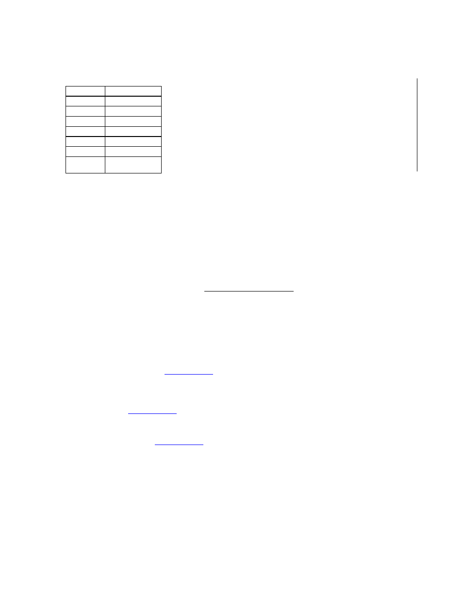
Pin number
Function
1-9
NC
10
B- (GND/CASE)
11
OUTPUT
12
NC
13
B+ (see note 5)
14-19
NC
20
B+ (optional)
(see note 5)