Fig. 1 package dimensions and terminal connections, Figure. 1, Package dimensions and terminal connections – Q-Tech QT625C User Manual
Page 6: Terminal connections
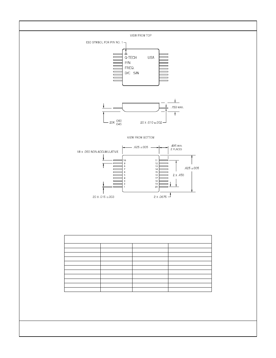
NOTES:
1. Dimensions are in inches.
2. Lead numbers are for reference only and are not marked on the unit.
3. All pins with function NC may not be connected as external tie or connections, except they may be tied to
Ground.
N/C
20
GND/CASE
10
N/C
19
N/C
9
N/C
18
N/C
8
N/C
17
N/C
7
N/C
16
N/C
6
GND/CASE *
15
N/C
5
N/C
14
N/C
4
V
CC
13
N/C
3
GND/CASE *
12
N/C
2
OUTPUT
11
N/C
1
CONNECTION
TERMINAL NO.
CONNECTION
TERMINAL NO.
TERMINAL CONNECTIONS
* Additional optional Ground connections may be connected to circuit ground plane for minimum
overshoot/ringing when driving capacitive loads.
FIGURE 1. PACKAGE DIMENSIONS AND TERMINAL CONNECTIONS
THIS DOCUMENT IS CONSIDERED PROPRIETARY TO Q-TECH CORPORATION
DO NOT COPY OR DISTRIBUTE WITHOUT Q-TECH CORPORATION APPROVAL
Q-Tech Corporation
10150 W. Jefferson Blvd.
Culver City, CA. 90232
Specification number: QT625C rev. F
Sheet 5 of 5