Q-tech, Low profile qt84, Reflow profile – Q-Tech QT84 User Manual
Page 4: Embossed tape and reel information for qt84, Environmental and mechanical specifications, 4 of 6
4 of 6
Q-TECH Corporation - 10150 W. Jefferson Boulevard, Culver City 90232 - Tel: 310-836-7900 - Fax: 310-836-2157 - www.q-tech.com
LOW PROFILE QT84
MINIATURE SMD CRYSTAL OSCILLATORS
1.8 to 5.0Vdc - 500kHz to 160MHz
Q-TECH
CORPORATION
QPDS-0003, Rev G, February 2013 (ECO# 10720)
Vdd
GND
0.1xVdd
0.9xVdd
VOH
VOL
Tr
Tf
TH
T
0.5xVdd
SYMMETRY = x 100%
TH
T
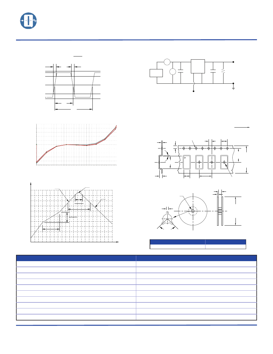
Output Waveform (Typical)
Frequency vs. Temperature Curve
Test Circuit
The Tristate function on pin 1 has a built-in pull-up resistor so it can be left
floating or tied to Vdd without deteriorating the electrical performance.
Reflow Profile
0
20
40
60
80 100 120 140 160 180 200 220 240 260 280 300 320 340 360 380 400 420
Time (s)
25
50
75
100
125
150
175
200
225
250
TEMP(*C)
0
60s min.
120s max.
60s min.
120s max.
225º min.
240º max.
60s min.
150s max.
240º
Ramp down (6ºC/s Max)
Ramp up (3ºC/s Max)
TYPICAL REFLOW PROFILE FOR Sn-Pb ASSEMBLY
Embossed Tape and Reel Information for QT84
Dimensions are in mm. Tape is compliant to EIA-481-A.
Environmental Test
Test Conditions
Temperature cycling
MIL-STD-883, Method 1010, Cond. B
Constant acceleration
MIL-STD-883, Method 2001, Cond. A, Y1
Seal: Fine and Gross Leak
MIL-STD-883, Method 1014, Cond. A and C
Vibration sinusoidal
MIL-STD-202, Method 204, Cond. D
Shock, non operating
MIL-STD-202, Method 213, Cond. I
Resistance to solder heat
MIL-STD-202, Method 210, Cond. B
Resistance to solvents
MIL-STD-202, Method 215
Solderability
MIL-STD-202, Method 208
ESD Classification
MIL-STD-883, Method 3015, Class 1 HBM 0 to 1,999V
Moisture Sensitivity Level
J-STD-020, MSL=1
Reel size (Diameter in mm) Qty per reel (pcs)
178
1,000
-
-
Output
Ground
4
3
2
0.1µF
15pF
1
Tristate Function
Power
supply
10k
mA
Vdc
+
+
+
(*)
or
0.01µF
QT84
(*) CL includes probe and jig capacitance
Typical test circuit for CMOS logic
Environmental and Mechanical Specifications
-50
-40
-30
-20
-10
0
10
20
30
40
50
-55 -50 -45 -40 -35 -30 -25 -20 -15 -10 -5 0
5 10 15 20 25 30 35 40 45 50 55 60 65 70 75 80 85 90 95 100 105
Frequency Stability (PPM)
Temperature (°C)
FVT QT84HC6-3.6864MHz
Ø178±1
26
FEEDING (PULL) DIRECTION
Ш13.0±0.5
120°
2.5
0.16
Ш1.5
12±0.1
2.0
1.75±0.1
0.3±.005
2.0±0.1
24.0±0.3
5.72±0.1
4.0±0.1
or
Ш330±1
Ш1.5
7.70
11.5
5°Max
P/N
FREQUENCY
D/C S/N